Data transmission method and apparatus using multiple scrambling codes

a data transmission and code technology, applied in the field of data transmission methods, can solve problems such as ineffective use of the transmission channel as could be desired

Inactive Publication Date: 2006-03-30
LAPIS SEMICON CO LTD
View PDF2 Cites 26 Cited by
  • Summary
  • Abstract
  • Description
  • Claims
  • Application Information

AI Technical Summary

Benefits of technology

[0010] An object of the present invention is to enable a transmission channel to be used effectively

Problems solved by technology

Due to the additional transmission overhead caused by such bits, the

Method used


Image

  • Data transmission method and apparatus using multiple scrambling codes
  • Data transmission method and apparatus using multiple scrambling codes
  • Data transmission method and apparatus using multiple scrambling codes

Examples


Embodiment Construction

[0020] An embodiment of the invention will now be described with reference to the attached drawings, in which analogous elements are indicated by analogous reference characters.

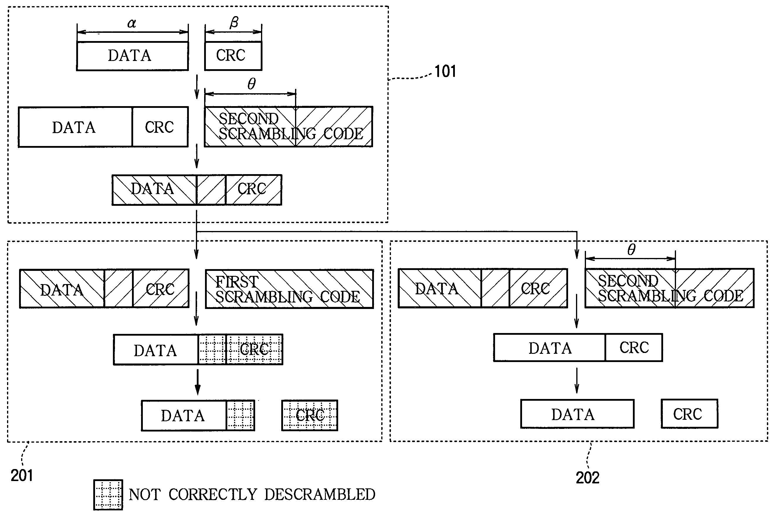
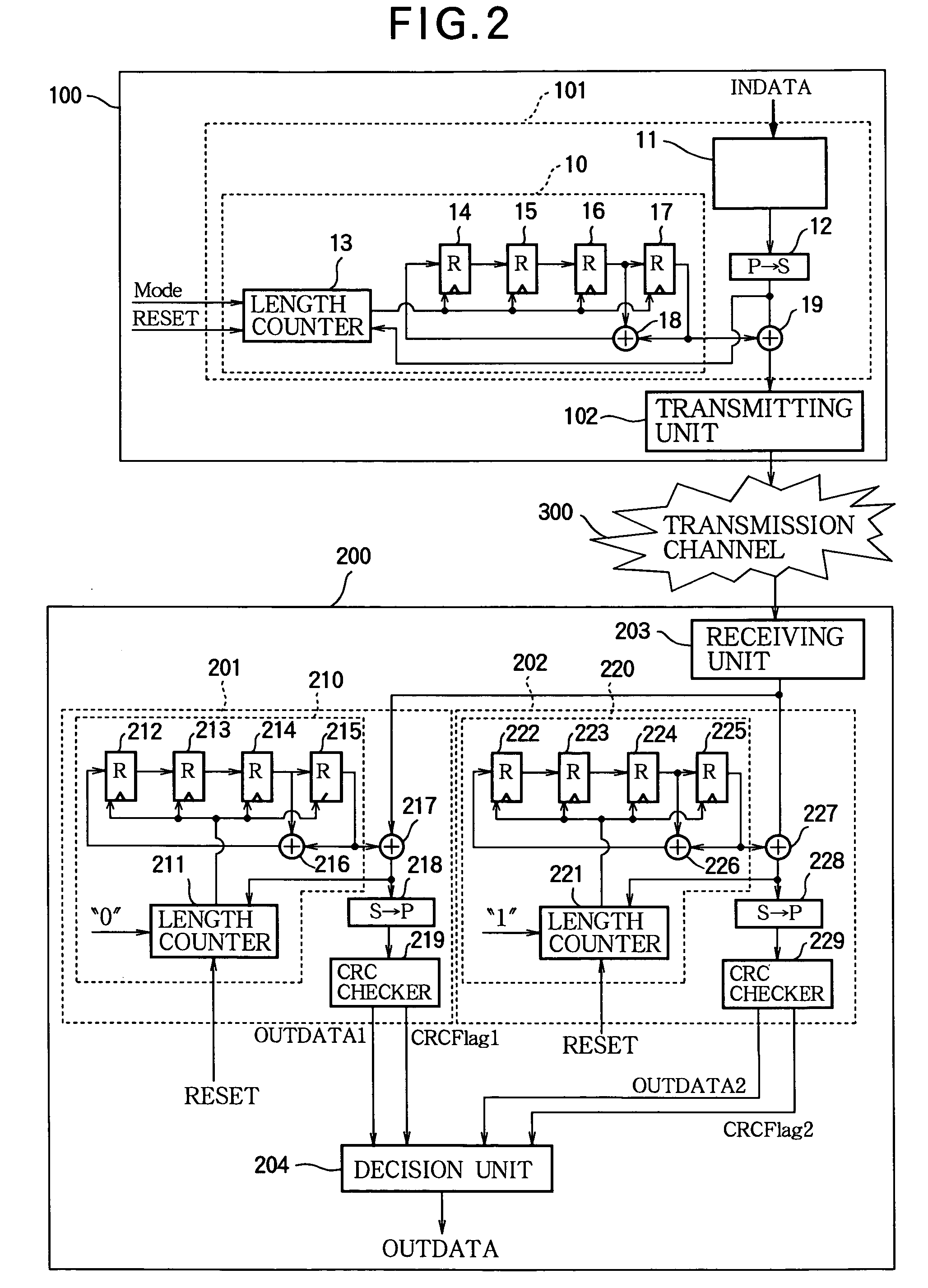
[0021] Referring to FIG. 2, the embodiment is a data transmission system comprising a data transmitting apparatus 100, a receiving apparatus 200, and transmission channel 300. The data transmitting apparatus 100 comprises an encoder 101 and a transmitting unit 102. The receiving apparatus 200 comprises a first decoder 201, a second decoder 202, a receiving unit 203, and a decision unit 204.

[0022] The encoder 101 comprises a scrambling code generator 10, a CRC inserter 11, a parallel-to-serial converter 12, and an exclusive-OR (XOR) gate 19. The first decoder 201 comprises a first scrambling code generator 210, an XOR gate 217, a serial-to-parallel converter 218, and a CRC checker 219. The second decoder 202 comprises a second scrambling code generator 220, an XOR gate 227, a serial-to-parallel converter 228...


PUM


Abstract

A packet including data and a cyclic redundancy check code is encoded by using a selectable one of N scrambling codes (N>1). The encoded packet is transmitted and received, then decoded N times by using the N scrambling codes. The cyclic redundancy check code is used to decide which one of the N scrambling codes enabled the encoded packet to be decoded correctly, and the correctly decoded data are used. Packets with different formats, in particular with headers of different lengths, can be distinguished by the use of different scrambling codes, so that different formats can be employed without the need to transmit extra data to indicate which format has been used.

Description

BACKGROUND OF THE INVENTION [0001] 1. Field of the Invention [0002] The present invention relates to a data transmission method in which the transmitted data are scrambled (encoded) by a predetermined rule at the transmitting end to prevent concentration of power caused by a run of identical bits, and descrambled (decoded) at the receiving end. The invention also relates to a data transmission system, a data transmitter, and a data receiver employing this method. [0003] 2. Description of the Related Art [0004]FIG. 1 shows a conventional data transmission system comprising a transmission channel 300, a data transmitting apparatus 400, and a data receiving apparatus 500. The data transmitting apparatus 400 comprises an encoder 401 and a transmitting unit 402. The data receiving apparatus 500 comprises a decoder 501 and a receiving unit 502. The encoder 401 comprises a scrambling code generator 40 and an exclusive-OR (XOR) gate 46. The decoder 501 comprises a scrambling code generator ...

Claims


Application Information

Patent Timeline
IPC IPC(8): H04N7/167G09C1/00H03M13/09H03M13/15H04L1/00
CPCH04L9/3236H04L9/065
Inventor YAMAZAKI, MASATO
Owner LAPIS SEMICON CO LTD
Why Eureka
Try Eureka