Piezoelectric MEMS element and tunable filter equipped with the piezoelectric MEMS element

a technology of piezoelectric mems and element, applied in the direction of positive displacement liquid engine, machine/engine, generator/motor, etc., can solve the problem of limited use of variable capacity/diode, the amount of displacement generated by voltage application to be changed, and the difficulty of maintaining the capacitance value before and after chang

Inactive Publication Date: 2006-03-30
KK TOSHIBA
View PDF6 Cites 43 Cited by
  • Summary
  • Abstract
  • Description
  • Claims
  • Application Information

AI Technical Summary

Benefits of technology

[0010] An object of the present invention is to provide a piezoelectric MEMS element, which permits maintaining constant the distance between the movable electrode and the stationary electrode in a MEMS type var...

Problems solved by technology

However, the variable capacity/diode has a capacitance varying range that is only about 5 times as much as the reference capacitance value, and the quality coefficient (Q value) of the variable capacity/diode denoting the smallness of the loss is small, i.e., about 20 to 30, and, thus, the use of the variable capacity/diode is currently limited.
The particular construction gives rise to the problems that a slight residual stress in the material constituting the beam causes the...

Method used


Image

  • Piezoelectric MEMS element and tunable filter equipped with the piezoelectric MEMS element
  • Piezoelectric MEMS element and tunable filter equipped with the piezoelectric MEMS element
  • Piezoelectric MEMS element and tunable filter equipped with the piezoelectric MEMS element

Examples


first embodiment

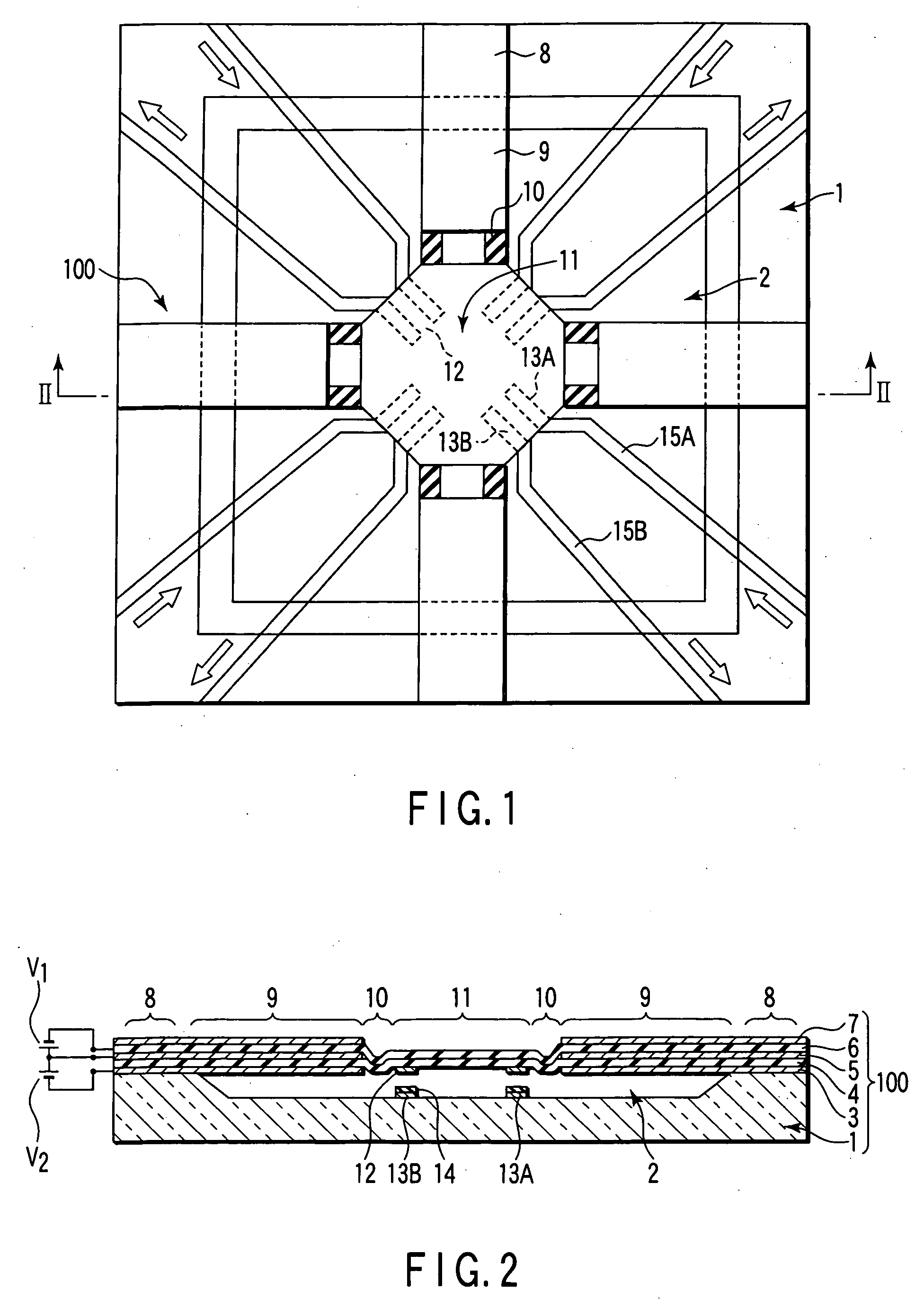
[0063]FIG. 1 is a plan view schematically showing the construction of a MEMS type variable capacity or capacitor having a piezoelectric driving mechanism of a beam structure supported on both sides according to a first embodiment of the present invention, and FIG. 2 is a cross sectional view along the line II-II shown in FIG. 1.

[0064] As shown in FIG. 1, a recess 2 that is substantially square as viewed from above is formed in an insulating substrate 1. For example, the recess 2 is shaped substantially square. It should be noted, however, the shape of the recess 2 is not limited to a squarer shape. A band-like laminate structure having a so-called “bimorph structure”, which constitutes a piezoelectric driving mechanism 100 and is substantially cross-shaped, is formed on the substrate 1 in a manner to cross the space above recess 2. The laminate structure extends from the peripheral region of the substrate 1 surrounding the recess 2 in a manner to form a substantially cross-shaped c...

second embodiment

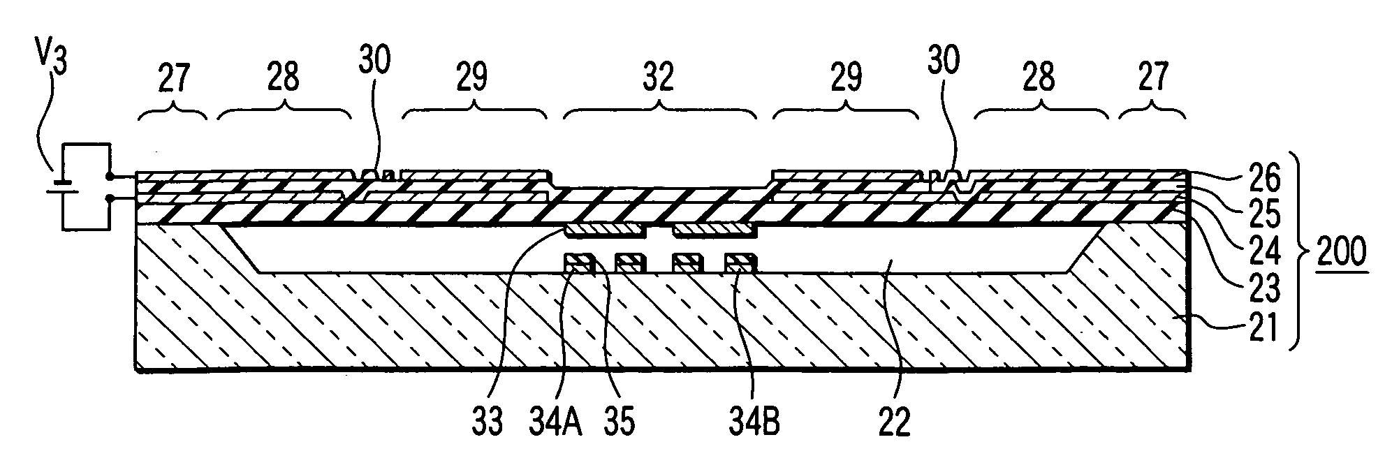
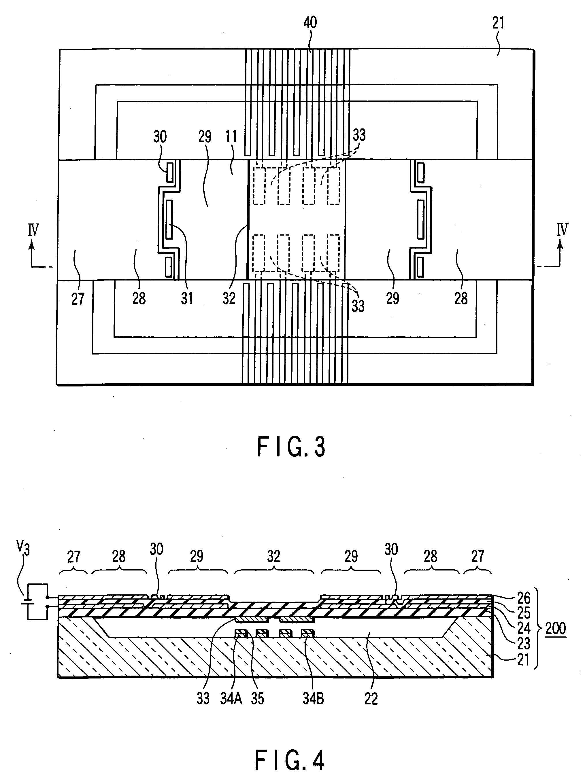
[0070] A piezoelectric driving MEMS type variable capacity or capacitor according to a second embodiment of the present invention will now be described with reference to FIGS. 3 and 4. FIG. 3 is a plan view schematically showing the construction of a MEMS type variable capacity having a piezoelectric driving mechanism of a beam structure supported on both sides, and FIG. 4 is a cross-sectional view along the line IV-IV shown in FIG. 3.

[0071] As shown in the drawings, a recess 22 that is substantially oblong as viewed from above is formed in the upper surface region of an insulating substrate 21. In this embodiment, the recess 22 is shaped substantially oblong. However, the recess 22 is not limited to an oblong recess. Formed above the recess 22 included in the substrate 21 is a so-called “unimorph structure”, i.e., a laminate structure constituting a piezoelectric driving mechanism 200 and of a support film 23, a lower electrode 24, a piezoelectric film 25, and an upper electrode 2...

third embodiment

[0078] A piezoelectric driving MEMS type variable capacity or capacitor according to a third embodiment of the present invention will now be described with reference to FIGS. 5 and 6. FIG. 5 is a plan view schematically showing the construction of a piezoelectric driving MEMS type variable capacity having a piezoelectric driving mechanism of a cantilever structure, and FIG. 6 is a cross-sectional view along the line VI-VI shown in FIG. 5.

[0079] As shown in the drawing, a so-called “unimorph structure”, i.e., the laminate structure in the driving section, i.e. driving beam structure 107 including a lower electrode 103, a piezoelectric film 104, an upper electrode 105, and a support film 106, is formed on an insulating substrate 101 with an anchor 102 used as a fulcrum. In this Embodiment, each of the lower electrode 103 and the upper electrode 105 is formed of an Al film having a thickness of 200 nm. Also, the piezoelectric film 104 is formed of an AlN film oriented in the c-axis an...


PUM


Abstract

In a MEMS type variable capacity having a piezoelectric driving mechanism, a movable head having movable electrodes are arranged thereon, stationary electrodes is positioned to face the movable electrodes, and a piezoelectric driving beam structure is joined to the movable head and have one end fixed to the substrate. The movable electrode and the stationary electrode form a variable capacity. In the variable capacity, the distance and capacitance between the movable electrode and the stationary electrode of the variable capacity can be maintained constant so as to realize a reproducibility and a reliable controllability.

Description

CROSS-REFERENCE TO RELATED APPLICATIONS [0001] This application is based upon and claims the benefit of priority from prior Japanese Patent Application No. 2004-278264, filed Sep. 24, 2004, the entire contents of which are incorporated herein by reference. BACKGROUND OF THE INVENTION [0002] 1. Field of the Invention [0003] The present invention relates to a piezoelectric MEMS (Micro-electro-mechanical System) element and a tunable filter, particularly, to a variable capacity having a piezoelectric driving mechanism utilizing a piezoelectric thin film. [0004] 2. Description of the Related Art [0005] A variable capacity / diode utilizing a change in the thickness of the depletion layer in the PN junction is known as a conventional variable capacity or capacitor. However, the variable capacity / diode has a capacitance varying range that is only about 5 times as much as the reference capacitance value, and the quality coefficient (Q value) of the variable capacity / diode denoting the smalln...

Claims


Application Information

Patent Timeline
IPC IPC(8): F04B43/00F04B17/00
CPCH01G5/16H01H57/00H01H2057/006H03H2210/033H03H9/605H03H2007/008H03H2210/025H03H9/542
Inventor KAWAKUBO, TAKASHINAGANO, TOSHIHIKOABE, KAZUHIDENISHIGAKI, MICHIHIKOONO, TOMIO
Owner KK TOSHIBA
Why Eureka
Try Eureka