Piston compressor, particularly hermetical refrigerant compressor

a compressor and hermetical technology, applied in the direction of positive displacement pump components, liquid fuel engine components, positive displacement liquid engines, etc., can solve the problems of large heating of suction gas, large dead space in the upper dead end of the piston, etc., to improve the compressor efficiency, the effect of keeping the harmful space or the dead space very small

Inactive Publication Date: 2006-03-30
DANFOSS COMPRESSORS
View PDF18 Cites 42 Cited by
  • Summary
  • Abstract
  • Description
  • Claims
  • Application Information

AI Technical Summary

Benefits of technology

[0029] Preferably, the valve plate arrangement has a base plate, a suction valve plate and a pressure valve plate, the suction valve plate and the pressure valve plate being located on the side of the base plate facing the cylinder, the pressure valve plate forming at least one valve seat for the suction valve arrangement and the suction valve plate forming at least one valve seat for the pressure valve arrangement. As the pressure valve plate and the suction valve plate, which are usually made of spring steel, can be kept substantially thinner than the base plate, which must provide a certain mechanical stability, this contributes to keeping the harmful space or the dead space very small. This further improves the efficiency of the compressor.
[0030] Preferably, the suction valve plate, the pressure valve plate and the base plate are connected with each other by at least one circumferential, gas-tight annular joint, which penetrates the suction valve plate and the pressure valve plate and separates the suction valve arrangement from the pressure valve arrangement. Thus, the annular joint has two tasks. On the one side, it connects the suction valve plate, the pressure valve plate and the base plate. On the other hand, it seals the suction area against the pressure area, so that neither during a suction stroke nor during a pressure stroke gas can pass by the suction valves or pressure valves into the respective other area. Also this improves the efficiency of the compressor. The annular joint can, for example, be mad

Problems solved by technology

This design gives a considerable dead space in the upper dead end of the piston and a relatively large

Method used


Image

  • Piston compressor, particularly hermetical refrigerant compressor
  • Piston compressor, particularly hermetical refrigerant compressor
  • Piston compressor, particularly hermetical refrigerant compressor

Examples


Embodiment Construction

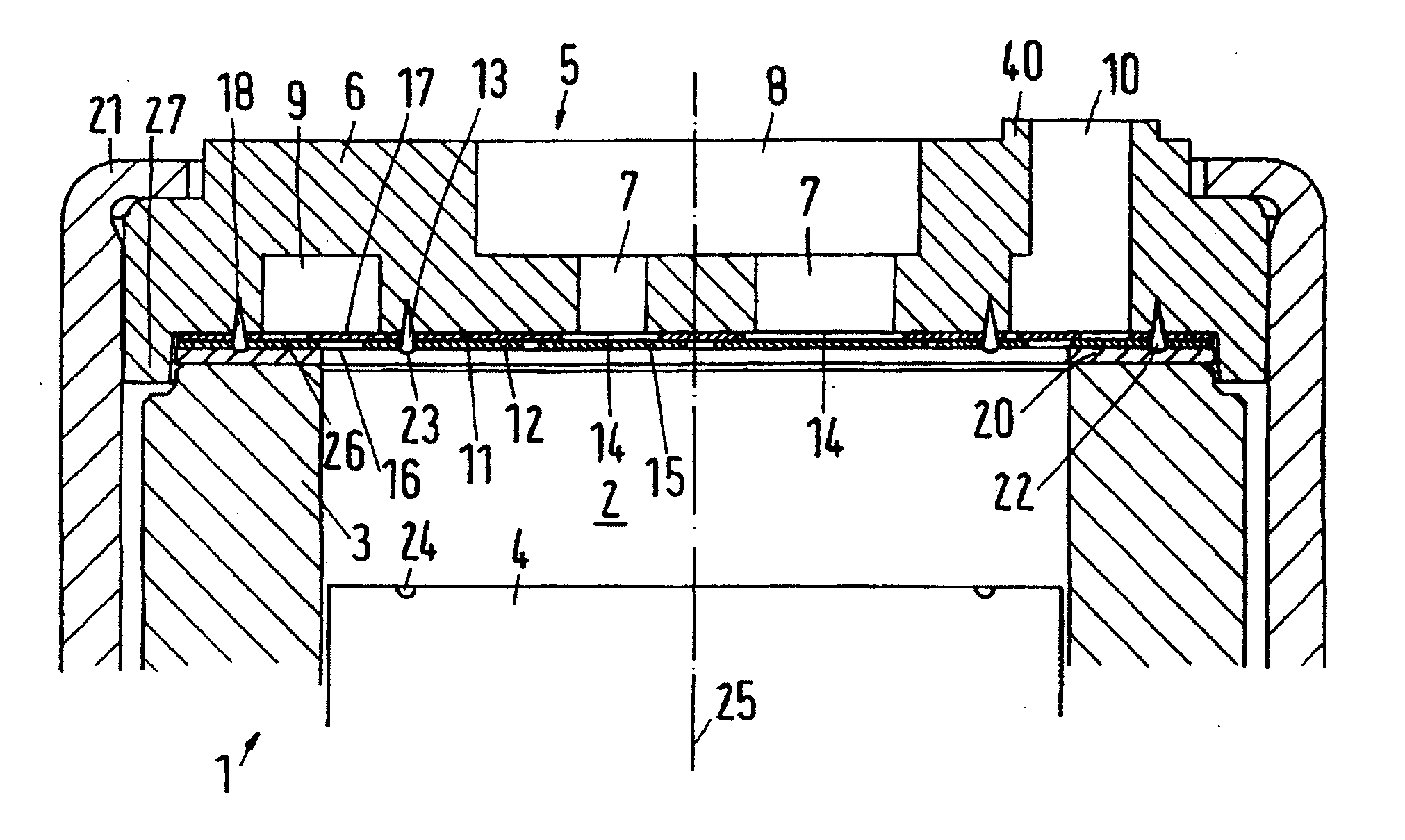
[0046] A piston compressor 1, only shown in sections in FIG. 1, has a compression chamber 2, which is bordered by a cylinder 3, a piston 4 and a valve plate arrangement 5. When the piston 4 reciprocates in the cylinder 3, the size of the compression chamber changes. When the piston 4 is moved away from the valve plate arrangement 5, the compression chamber 2 expands, and gas, for example a refrigerant gas, is sucked in. When the piston 4 is moved towards the valve plate arrangement 5, the gas in the compression chamber 2 is compressed and finally discharged.

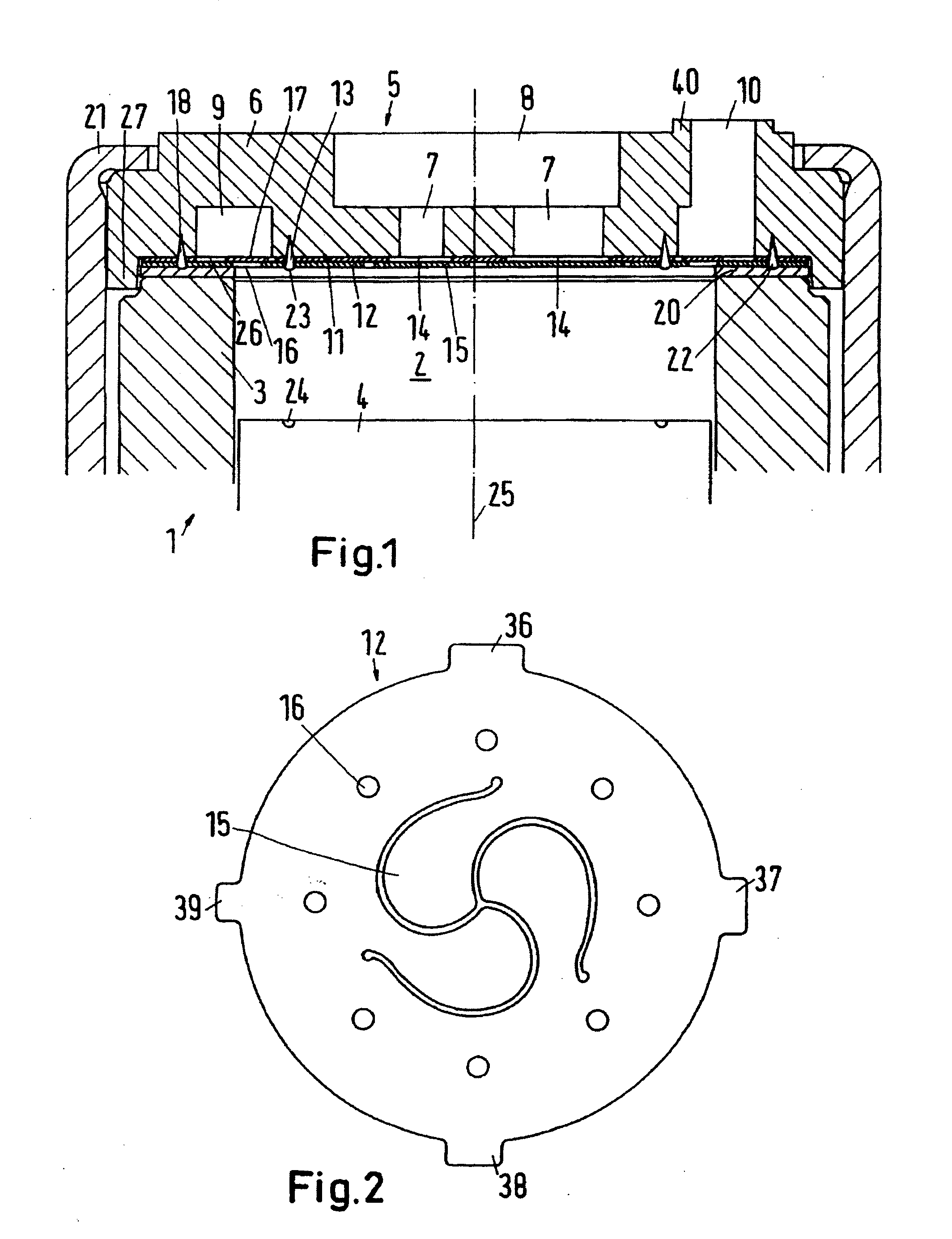
[0047] For the control of the gas flows, the valve plate arrangement 5 has a base plate 6, which is relatively massive, and provides the valve plate arrangement 5 with the largest share of its mechanical stability. The base plate 6 has several suction channels 7, which originate from a recess 8. One purpose of the recess 8 is the mounting of a suction muffler, not shown in detail.

[0048] Further, the base plate 6 has an annular ...


PUM


Abstract

The invention concerns a piston compressor (1), particularly a hermetical refrigerant compressor, with a compression chamber (2), which is bordered by a cylinder (3), a piston (4) and a valve plate arrangement (5), which has a suction valve arrangement (14, 15) and a pressure valve arrangement (16, 17). It is endeavoured to provide a piston compressor with a good efficiency. For this purpose, it is ensured that the suction valve arrangement (14, 15) opens into the compression chamber (2) in a central area of the cylinder (3) and the pressure valve arrangement (16, 17) has a plurality of pressure openings (16), which are located in an annular area surrounding the suction valve arrangement (14, 15).

Description

CROSS-REFERENCE TO RELATED APPLICATIONS [0001] Applicant hereby claims foreign priority benefits under U.S.C. § 119 from German Patent Application No. 10 2004 047 159.2 filed on Sep. 29, 2004, the contents of which are incorporated by reference herein. FIELD OF THE INVENTION [0002] The invention concerns a piston compressor, particularly a hermetical refrigerant compressor, with a compression chamber, which is bordered by a cylinder, a piston and a valve plate arrangement, which has a suction valve arrangement and a pressure valve arrangement. BACKGROUND OF THE INVENTION [0003] In the following, the invention will be described by way of a refrigerant compressor as an example of a piston compressor. However, it can also be used with other piston compressors. [0004] In a refrigerant compressor the compression chamber expands, when the piston is moved away from the valve plate arrangement. In this case, refrigerant gas is sucked into the compression chamber through the suction valve ar...

Claims


Application Information

Patent Timeline
IPC IPC(8): A61M1/00F04B53/00
CPCF04B39/108F04B39/1073
Inventor IVERSEN, FRANK HOLM
Owner DANFOSS COMPRESSORS
Why Eureka
Try Eureka