Cogeneration system and method for controlling the same

a cogeneration system and power generation technology, applied in the direction of combined combustion mitigation, lighting and heating apparatus, heating types, etc., can solve the problem of inability to maximize the efficiency of the system, and achieve the effect of maximizing facilitating the operation of the cogeneration device, and minimizing the utilization factor of the external power sour

Inactive Publication Date: 2007-01-25
LG ELECTRONICS INC
View PDF42 Cites 17 Cited by
  • Summary
  • Abstract
  • Description
  • Claims
  • Application Information

AI Technical Summary

Benefits of technology

[0030] The cogeneration system and the method for controlling the same in accordance with the invention have an advantage that it is easy to operate the cogeneration device because the operation of the cogeneration device can be controlled according to operation signals of the air conditioner, and have an effect that it is possible to make the best use of the generated electricity of the cogeneration device through an interconnection between the air conditioner and the cogeneration device.
[0031] Additionally, the air conditioner controller and the cogeneration device controller are supplied with electricity from an external power source, and the compressor, fan, etc. of the air conditioner are supplied with electricity from the generator, so that it is possible to properly use the generated electricity of the cogeneration system and the external power source, thereby maximizing the utilization of the generated electricity of the cogeneration device and minimizing the utilization factor of the external power source by
[0032] Additionally, the suction side of the compressor is pre-heated using waste heat recovered b the engine of the cogeneration device, so that the efficiency of the compressor is improved, to thus reduce unnecessary waiting time when driving the cogeneration device.
[0033] Additionally, if the operation signals outputted to the cogeneration device controller from a plurality of remote controls are all OFF signals, and the OFF signals are maintained for a predetermined time, the operation of the cogeneration device is stopped, thereby preventing a malfunction thereof.

Problems solved by technology

However, the cogeneration system in accordance with the prior art has a problem in that only the electricity produced by the generator 2 is supplied to the air conditioner 6, and the waste heat recovered by the engine 4 is only utilized for hot water supply, warm water, or the like in the heat demanding site, so that it is impossible to maximize the efficiency of the system.

Method used


Image

  • Cogeneration system and method for controlling the same
  • Cogeneration system and method for controlling the same
  • Cogeneration system and method for controlling the same

Examples


Embodiment Construction

[0038] Hereinafter, an exemplary embodiment of a cogeneration system and a method for controlling the same in accordance with the invention will be described with reference to the accompanying drawings.

[0039] There may be a plurality of exemplary embodiments of the cogeneration system and the method for controlling the same in accordance with the invention, but the most preferred embodiment will be described hereinafter.

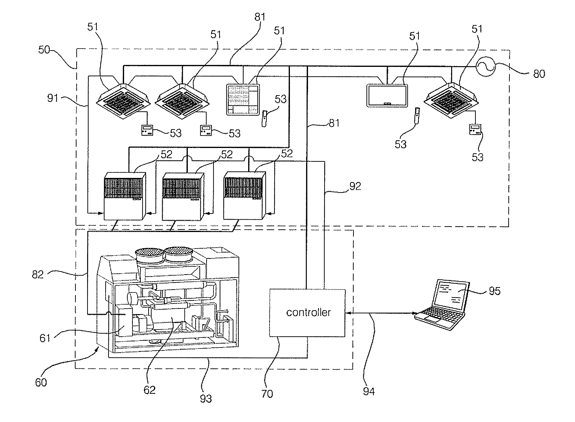
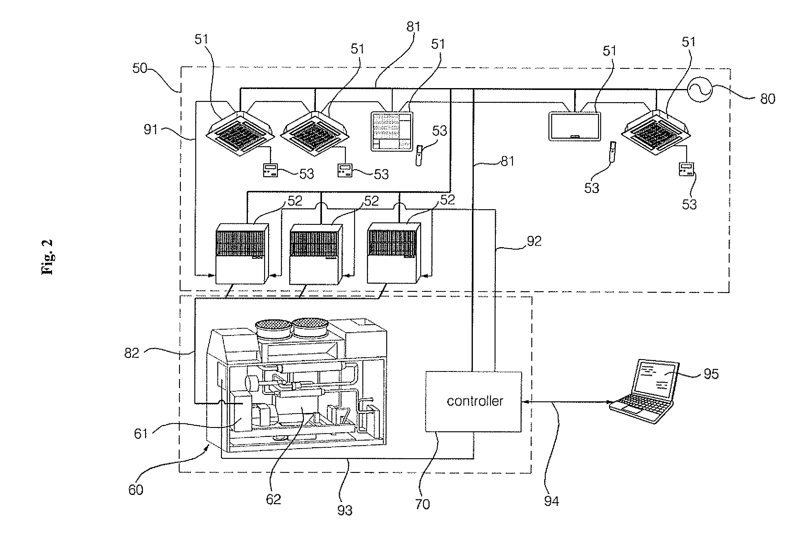
[0040]FIG. 2 is a block diagram schematically showing a cogeneration system in accordance with the present invention.

[0041] The cogeneration system in accordance with the invention, includes, as shown in FIG. 2, an air conditioner 50, a cogeneration device 60 for supplying electricity and heat to the air conditioner 50, and a controller 70 for controlling the operation of the cogeneration device 60 according to operation signals from the air conditioner 50.

[0042] A description of the air conditioner 50 will be made with respect to a heat pump type air conditioner...


PUM


Abstract

A cogeneration system and a method for controlling the same have an advantage that it is easy to operate a cogeneration device because the operation of the cogeneration device can be controlled according to operation signals of an air conditioner, and have an effect that it is possible to make the best use of the generated electricity of the cogeneration device through an interconnection between the air conditioner and the cogeneration device.

Description

[0001] The present disclosure relates to subject mater contained in priority Korean Application No. 10-2005-0061798, filed on Jul. 8, 2005, which is herein expressly incorporated by reference in its entirety. BACKGROUND CF THE INVENTION [0002] 1. Field of the Invention [0003] The present invention relates to a cogeneration system, and more particularly to, a cogeneration system, which operates an engine and a generator according to operation signals from an air conditioner, and which uses electricity produced by the generator and waste heat recovered by the engine for the air conditioner, thereby improving the efficiency of the system, and a method for controlling the same. [0004] 2. Description of the Background Art [0005] In general, a cogeneration system is a system that can produce both electricity and heat from a single energy source. The electricity produced by the cogeneration system is supplied for use to electrical household appliances, such as various kinds of household li...

Claims


Application Information

Patent Timeline
Patent Type & Authority Applications(United States)
IPC IPC(8): F24D1/00
CPCF24F11/0086F24F2011/0067Y02E20/14F25B2600/07F25B27/00Y02P80/15F24F11/30F24F11/54F24F11/46F24F11/56F25B27/02
Inventor CHOI, CHANG MINCHOE, YEONG SEOPCHOI, WON JAELEE, JAE WONCHUNG, BAIK YOUNGCHANG, SE DONG
Owner LG ELECTRONICS INC
Why Eureka
Try Eureka