Cooling apparatus, gas turbine system using cooling apparatus, heat pump system using cooling system, cooling method, and method for operating cooling apparatus

Inactive Publication Date: 2009-03-05
HITACHI LTD
View PDF8 Cites 17 Cited by
  • Summary
  • Abstract
  • Description
  • Claims
  • Application Information

AI Technical Summary

Benefits of technology

[0008]In accordance with the present invention, it is possible to provide a coolin

Problems solved by technology

Since it is necessary to set a margin in consideration of the above, there is a limit

Method used


Image

  • Cooling apparatus, gas turbine system using cooling apparatus, heat pump system using cooling system, cooling method, and method for operating cooling apparatus
  • Cooling apparatus, gas turbine system using cooling apparatus, heat pump system using cooling system, cooling method, and method for operating cooling apparatus
  • Cooling apparatus, gas turbine system using cooling apparatus, heat pump system using cooling system, cooling method, and method for operating cooling apparatus

Examples


first embodiment

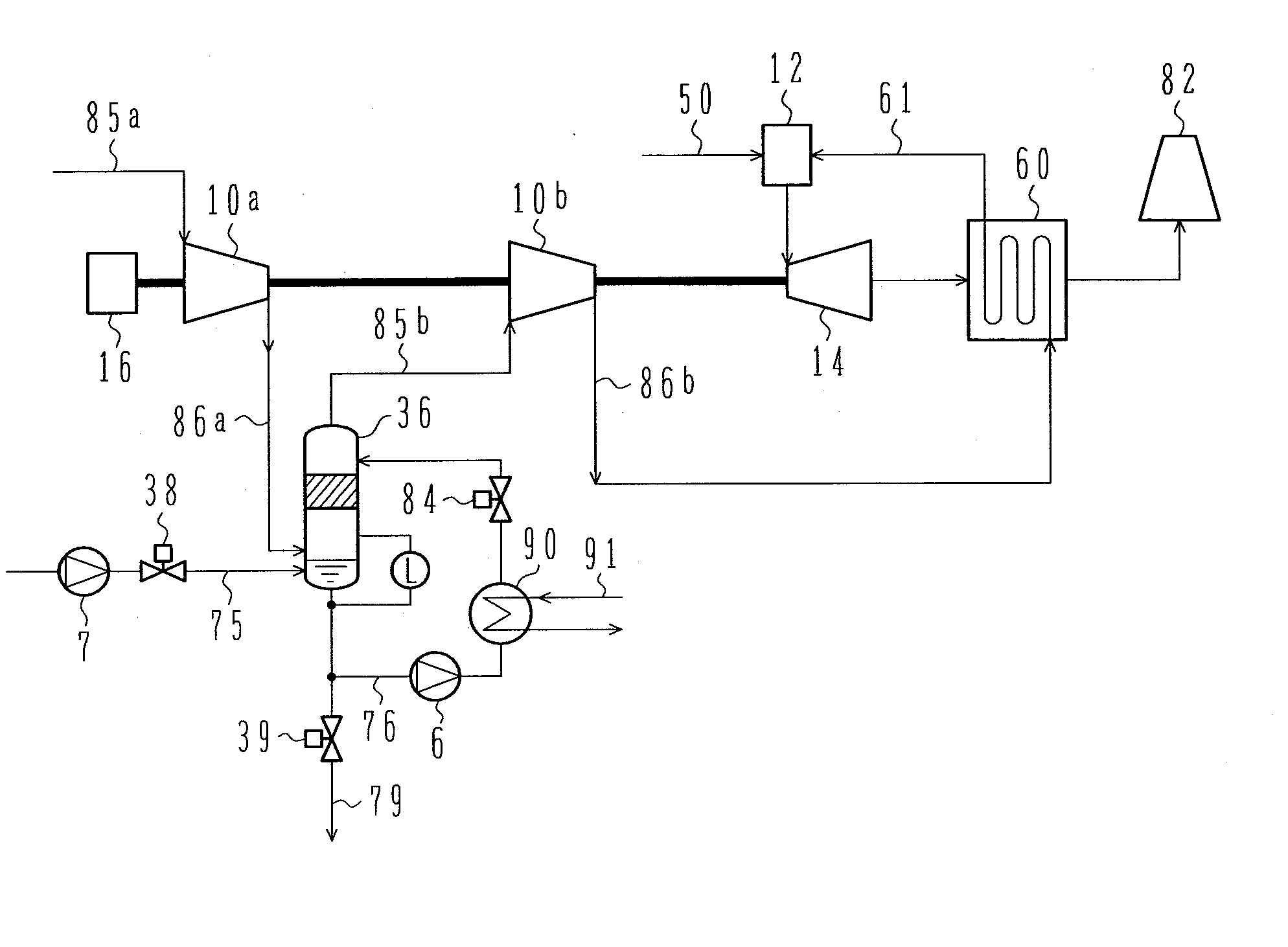
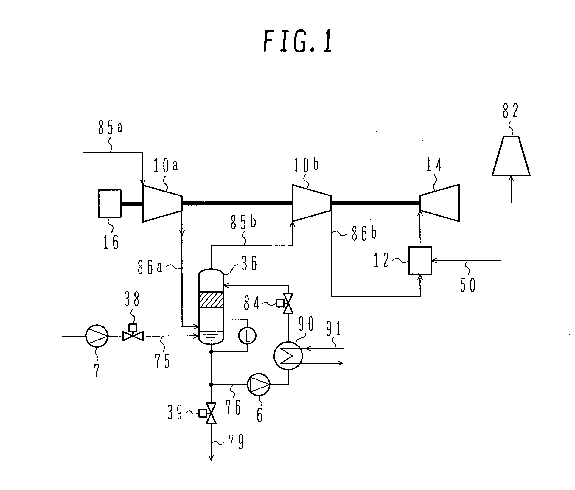
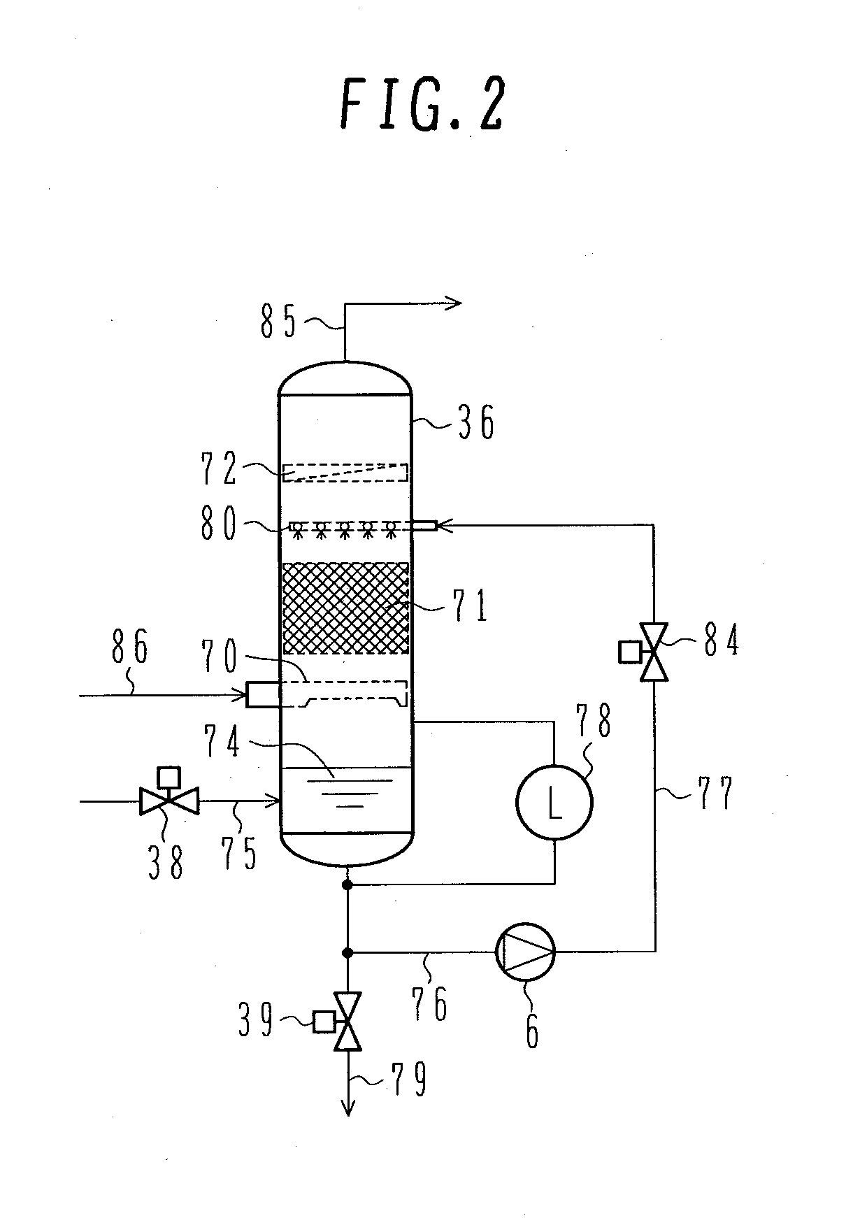
[0065]A first embodiment of the present invention will be explained in detail below with reference to FIG. 3. FIG. 3 illustrates a recuperated-cycle gas turbine system having an intercooling system of a compressor according to an embodiment of the present invention.

[0066]The recuperated-cycle gas turbine system according to the present embodiment mainly includes compressors 10a and 10b which compress air, a recuperator 60 which heats compressed air obtained by compressing air with the compressor 10b using exhaust gas of a gas turbine, a combustor 12 which combusts air heated by the recuperator 60 and fuel 50 to generate combustion gas, a turbine 14 which is driven by the above-mentioned combustion gas generated by the combustor 12, and a stack 82 which discharges combustion gas as exhaust gas, the combustion gas being produced by driving the turbine 14 and performing heat exchange with compressed air by the recuperator 60. The present embodiment assumes that the pressure ratio of th...

second embodiment

[0092]Another embodiment of a recuperated-cycle gas turbine system having an intercooling system according to the present invention will be explained below with reference to FIG. 4. FIG. 4 shows a recuperated-cycle gas turbine system having an intercooling system of compressor according to an embodiment of the present invention. The recuperated-cycle gas turbine system having the intercooling system shown in the first embodiment provides an effect of cooling compressed air by 100° C. or more and the amount of humidification for the compressed air is 0.6% by mass of air. The present embodiment indicates a recuperated-cycle gas turbine system having an intercooling system which provides a smaller effect of cooling compressed air and accordingly a larger effect of humidifying compressed air than the system shown in the first embodiment. The system shown in the present embodiment differs from the system shown in the first embodiment in that neither the heat exchanger 90 nor the cooling ...

third embodiment

[0099]Still another embodiment of the present invention will be explained below with reference to FIG. 9. FIG. 9 shows a steam heat pump system having an intercooling system of compressor according to a third embodiment of the present invention. The present embodiment differs from the first and second embodiments in that the fluid which flows in the compressors is steam instead of air.

[0100]The present embodiment mainly includes an evaporator 42 which evaporates liquid water 35 with the heat of warm water 40 introduced from outside under conditions below the atmospheric pressure to generate steam; compressors 110a, 110b, 110c, and 110d driven by a drive unit (not shown), which pressurize the steam generated by the evaporator 42; and a discharge pipe 25 which supplies the hot steam pressurized by the above-mentioned compressor 110d to a target location. Compressors 110a, 110b, 110c, and 110d are connected in series on the same shaft and configured to gradually raise the steam pressur...


PUM


Abstract

The amount of water to be injected in an intercooler is controlled to cool the compressed gas to the saturation temperature. It is difficult to adjust the amount of the water to be injected, however, since the temperature of the compressed gas at an intercooler outlet is actually higher than the saturation temperature. An intercooling system is configured so as to cool a gas to the saturation temperature without controlling the amount of water injection and thereby maintain the reliability of the compressor while improving the cooling efficiency.
The intercooling system is located between a plurality of compression stages of a gas compressor to cool the gas that has been in the compressor. A desired amount of liquid is sprinkled to cool the compressed gas while restraining inflow of the liquid into the compression stages.

Description

BACKGROUND OF THE INVENTION[0001]1. Field of the Invention[0002]The present invention relates to a cooling apparatus adapted to cool compressed fluid from a gas compressor which compresses air, steam, etc., a gas turbine system using a cooling apparatus, a heat pump system using a cooling apparatus, a cooling method, and a method for operating a cooling apparatus.[0003]2. Description of the Related Art[0004]Intercooling of a gas compressor which compresses air and steam is performed by a known system which cools a gas that has been compressed in a compressor by water injection. In connection with a method of cooling hot fluid like a gas compressed in a compression process of a compressor, JP-A-2005-274070 discloses an apparatus which injects desuperheated water into superheated steam to desuperheat the steam close to a saturation temperature.[0005]In accordance with a system which cools the compressed gas to about the saturation temperature through water injection in an intercooler ...

Claims


Application Information

Patent Timeline
IPC IPC(8): F02C7/143F25B27/00
CPCF04D29/5846F02C7/1435
Inventor ARAKI, HIDEFUMISHIBATA, TAKANORIHATAMIYA, SHIGEOTSUKAMOTO, MORIAKI
Owner HITACHI LTD
Why Eureka
Try Eureka