
Air conditioning system for vehicle

a technology for air conditioning systems and vehicles, applied in the direction of machines/engines, positive displacement liquid engines, light and heating apparatus, etc., can solve the problems of increased temperature of passenger compartments of vehicles, inconvenient condition of windows fogged, and occupants' discomfor

Active Publication Date: 2005-12-13
SHAREINTEL +1
View PDF11 Cites 18 Cited by
  • Summary
  • Abstract
  • Description
  • Claims
  • Application Information

AI Technical Summary

Benefits of technology

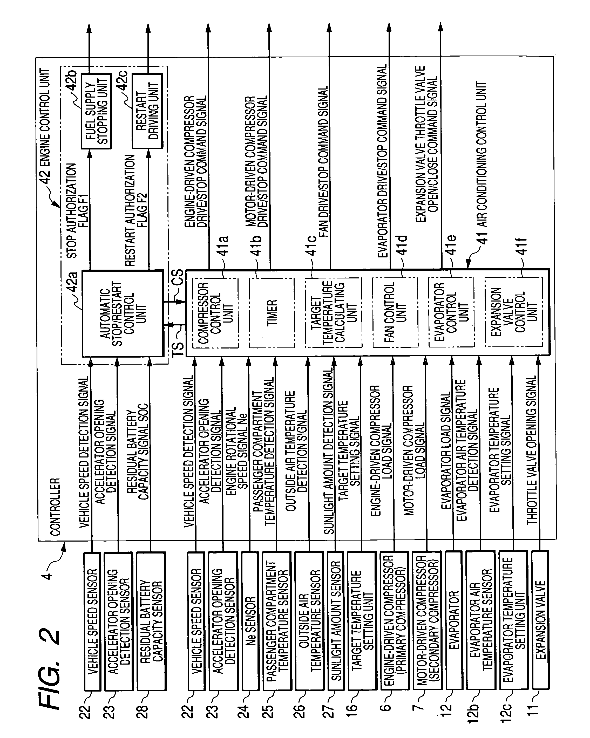
The invention is an air conditioning system for a vehicle that can improve both cooling and fuel economy. It achieves this by using two compressors, one driven by an engine and one driven by a motor. When the cooling demand is high, the engine-driven compressor is used, while when the cooling demand is low, the motor-driven compressor is used. This allows for better efficiency of the compressors and simultaneous improvement in cooling and fuel economy. Additionally, a timer is used to stop the engine-driven compressor after a certain amount of cooling has occurred, ensuring that the passenger compartment remains comfortable even when the engine is stopped.

Problems solved by technology

As a result, when the outside temperature is high or the sunlight is intense, the temperature of a passenger compartment of the vehicle increases, whereby there may occur a case where occupants feel uncomfortable.
On the contrary, when the outside temperature is low, the dehumidifying capability is lowered to be short, and breath expelled from the occupants increases the humidity inside the passenger compartment, causing an inconvenient condition where windows are fogged.

Method used


Image

  • Air conditioning system for vehicle
  • Air conditioning system for vehicle
  • Air conditioning system for vehicle

Examples


Embodiment Construction

[0022]An embodiment of an air conditioning system for a vehicle according to the invention will be described in detail below by reference to the accompanying drawings.

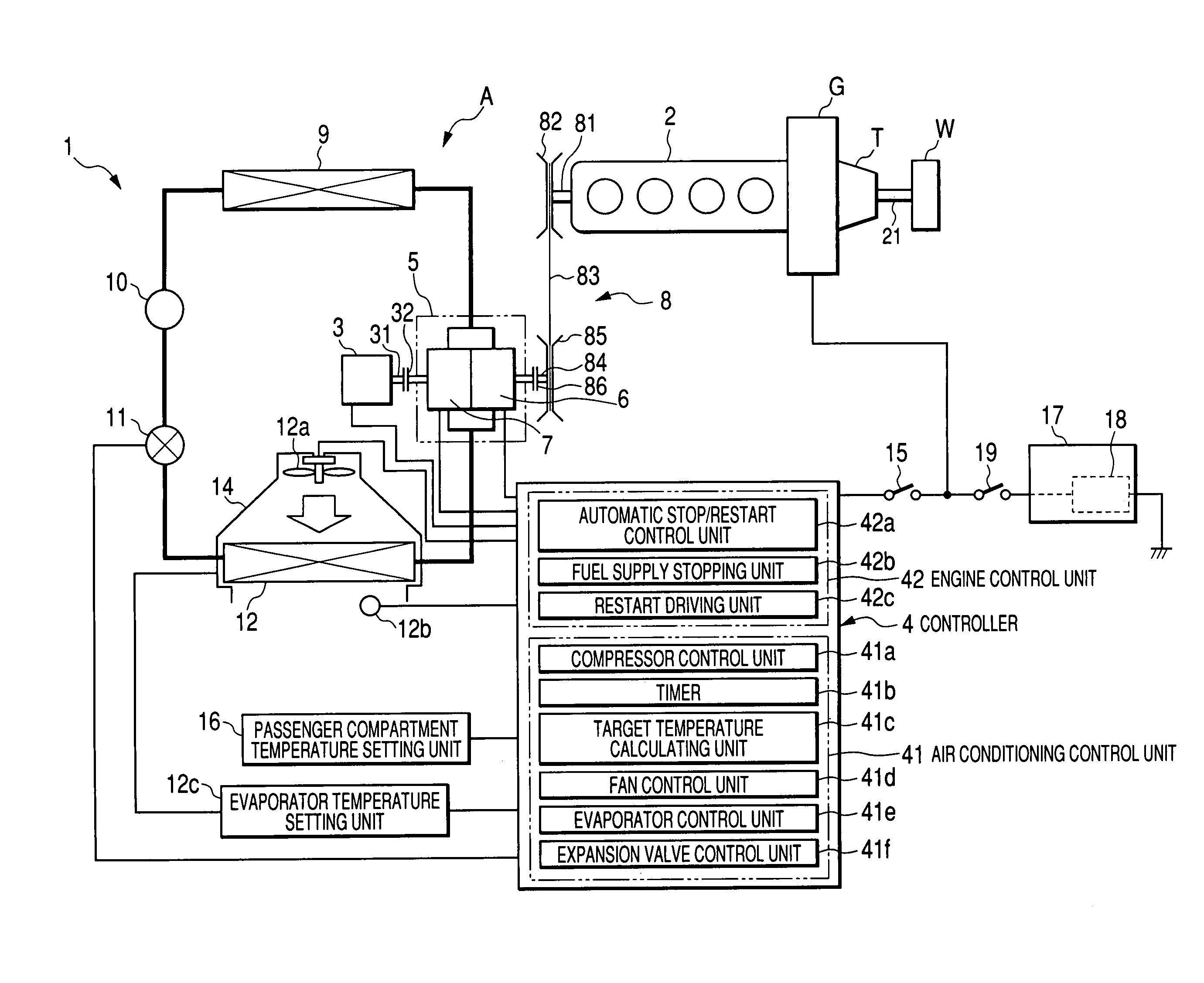
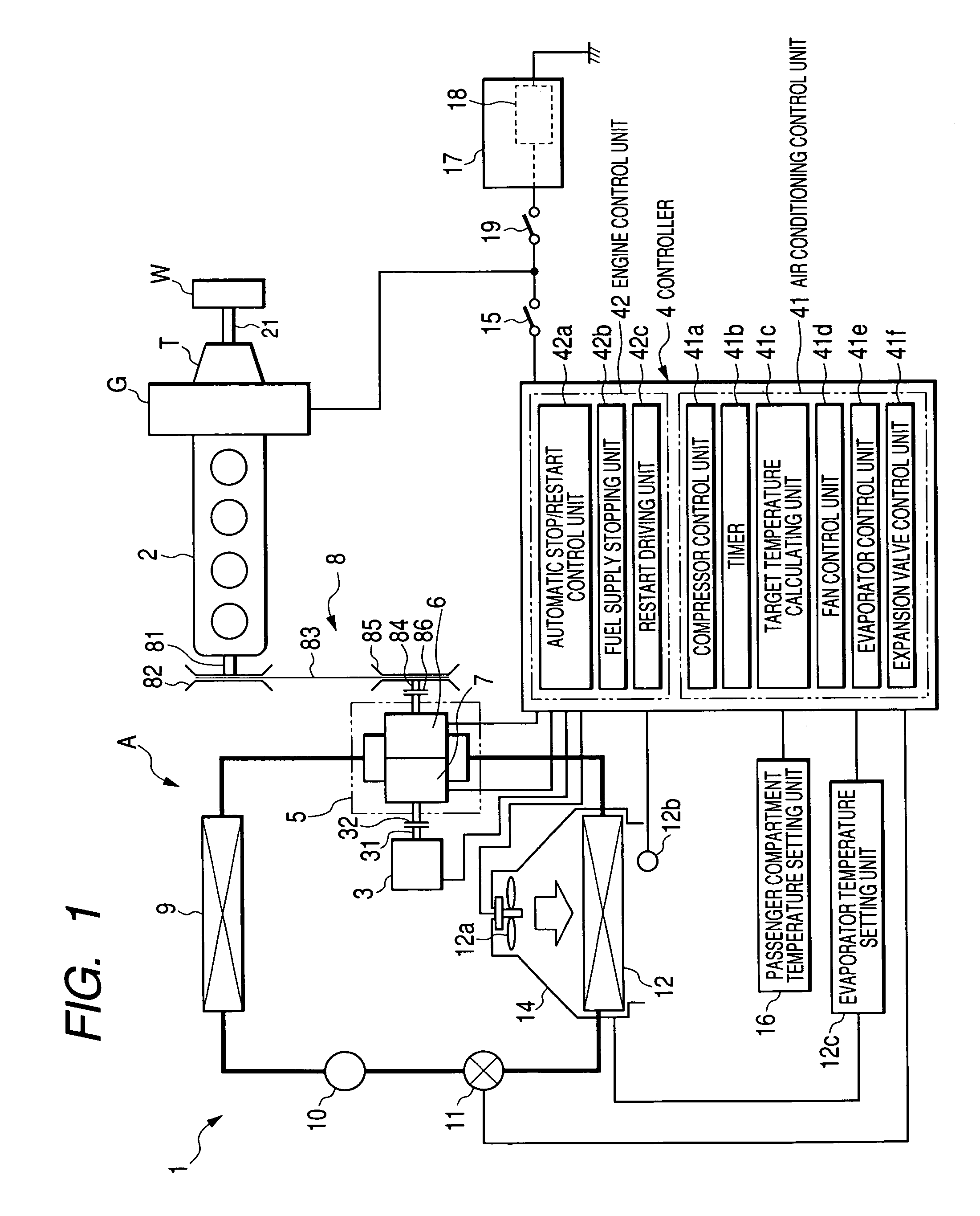
[0023]FIG. 1 is a block diagram showing an air conditioning system for a vehicle according an embodiment of the invention.

[0024]As shown in FIG. 1, an air conditioning system 1 for a vehicle is such as to operate based on, as driving sources, an engine 2 which is a driving source of a vehicle and a motor 3 for a motor-driven compressor 7.

[0025]While the air conditioning system 1 is optimum as a system that is installed in , for example, a vehicle provided with a stop-idling function (an automatic stop and restart function), the system may be installed either in the vehicle having such a function or in a vehicle having no such function.

[0026]Hereinafter, an embodiment of the invention will be described by taking as an example an air conditioning system 1 on a vehicle in which the stop-idling function is installed.

[0027]...


PUM


Abstract

An air conditioning system 1 includes a primary compressor (an engine-driven compressor 6) driven by a primary driving source (an engine 2) and a secondary compressor (a motor-driven compressor 7) driven by a secondary driving source (a motor 3). When a required cooling capability is equal to or greater than a predetermined value, the air conditioning system 1 causes the primary compressor (the engine-driven compressor 6) to be driven by the primary driving source (the engine 2) and adjusts the rotational speed of the secondary compressor (the motor-driven compressor 7), whereas when the required cooling capability is equal to or smaller than the predetermined value, the air conditioning system 1 causes the secondary compressor (the motor-driven compressor 7) to be driven by the secondary driving source (the motor 3) so as to control the rotational speed of the primary compressor (the engine-driven compressor 6).

Description

BACKGROUND OF THE INVENTION[0001]The present invention relates to an air conditioning system for a vehicle including a primary compressor which is driven by a primary driving source including an engine and a secondary compressor driven by a secondary driving source including a motor.[0002]Conventionally, there are known air conditioning systems for vehicle (hereinafter, referred simply to an “air conditioning system”) which use an engine driven compressor which uses a vehicular running engine as a driving source, an electric motor which is installed in an electric vehicle and a motor driven compressor which is used when the idling of an engine is stopped.[0003]In recent years, there is an increasing tendency to drastically promote the conservation of environment and improvement in fuel economy, and in conjunction with this tendency, the number of vehicles having a stop-idling function tends to increase. In a vehicle having such a stop-idling function, when the vehicle is stopped whi...

Claims


Application Information

Patent Timeline
Patent Type & Authority Patents(United States)
IPC IPC(8): B60H1/32F25B27/00F25B49/02
CPCB60H1/3205B60H1/322B60H1/3222B60H1/3223F25B49/022B60H2001/3261B60H2001/3266B60H2001/327B60H2001/3285B60H2001/3294F25B27/00F25B2327/001F25B2400/075F25B2500/27F25B2600/0253F25B2700/2104F25B2700/2106F25B2700/21173
Inventor IKURA, HIROSHIADACHI, HIROMITSUKUBOTA, MASAMICHIWATANABE, HIDEKIWAKOU, SHINICHIROU
Owner SHAREINTEL
Learn More