Water-injection type scroll air compressor

a scroll air compressor and water injection technology, applied in the direction of machines/engines, liquid fuel engines, positive displacement liquid engines, etc., can solve the problems of no description of the appropriate data range for the amount of water to be injected, and no presentation of any standards to be established, so as to reduce the pre-stopping operation time for drying and enhance the efficiency of the compressor

Active Publication Date: 2011-06-02
HITACHI IND EQUIP SYST CO LTD
View PDF8 Cites 16 Cited by
  • Summary
  • Abstract
  • Description
  • Claims
  • Application Information

AI Technical Summary

Benefits of technology

[0007]In general, before the compressor is stopped, dry operation is performed for a while (in further detail, operation with water injection off), for the user wishes to minimize the amount of water left in the compressor body. In addition to discharging the water from the compressor body, the pre-stopping dry operation of the compressor uses compression heat to dry the inside. The dry operation is intended to suppress compressor internal corrosion and water deterioration during the shutdown period, and to facilitate the next start of the compressor. In further detail, the dry operation takes place to suppress the acceleration of galvanic corrosion due to the stationary water sticking to the surface of a metal formed from a plurality of materials, and hence to suppress the acceleration of the internal corrosion which progresses more easily during the shutdown period than during compressor operation. A further purpose is to suppress increases in starting torque due to the fact that if water remains in the compressor body during the start of the compressor, the water will be several thousands times denser than air. A further purpose is to make it less likely for a compressor-starting failure or damage to the compressor body to result from the possible freezing of residual water particularly in cold areas. For these purposes, dry operation of the compressor takes place before it is stopped, and its internal drying during the dry operation can be accomplished more rapidly with a smaller amount of water injection under normal operating conditions. The improvement of efficiency and reduction in the operation time for drying are in a relationship of trade-off, such that it has traditionally been necessary for achieving both at the same time to be considered when determining the amount of water to be injected.
[0019]While enhancing the efficiency of the compressor, the present invention reduces the pre-stopping operation time for drying.

Problems solved by technology

Traditionally, however, no description has been given of an appropriate data range for the amount of water to be injected, nor has a presentation been given of any standards to be established.

Method used


Image

  • Water-injection type scroll air compressor
  • Water-injection type scroll air compressor
  • Water-injection type scroll air compressor

Examples


Embodiment Construction

[0025]Hereunder, an embodiment of the present invention will be described referring to the accompanying drawings.

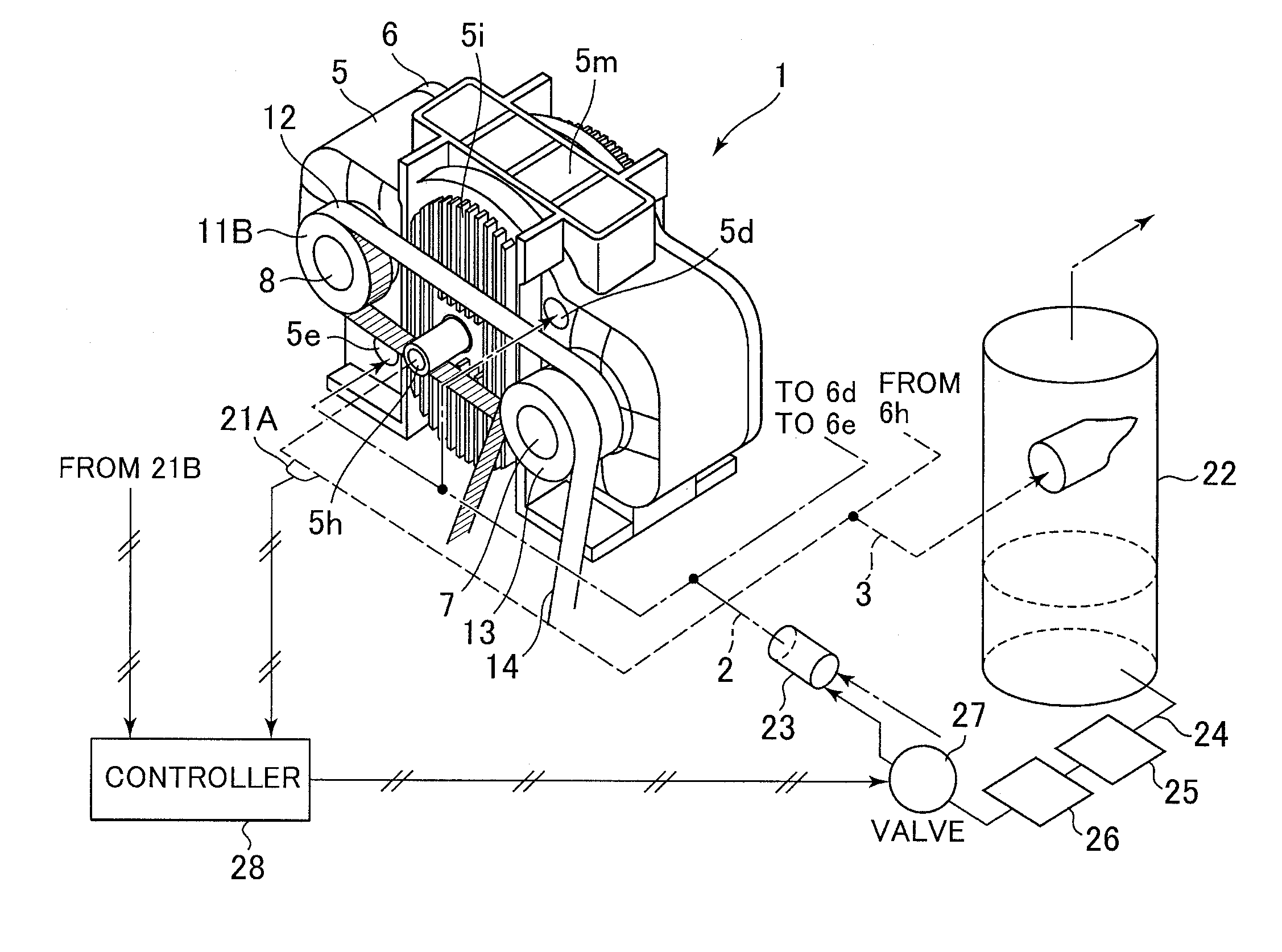
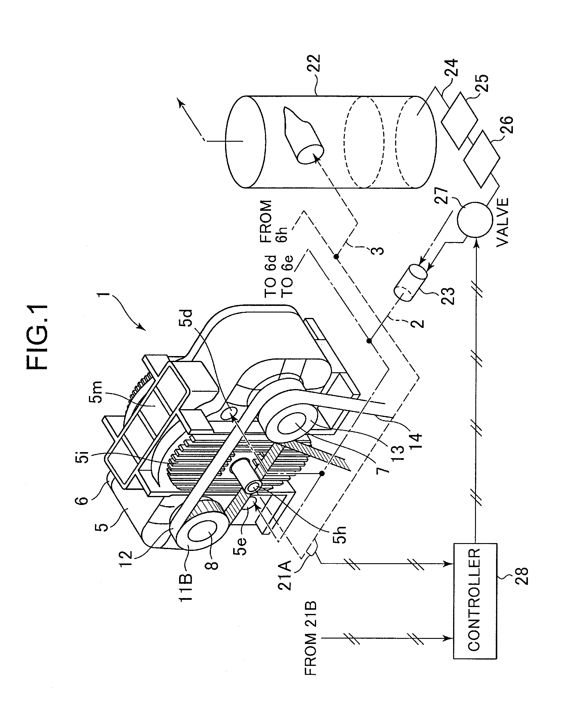
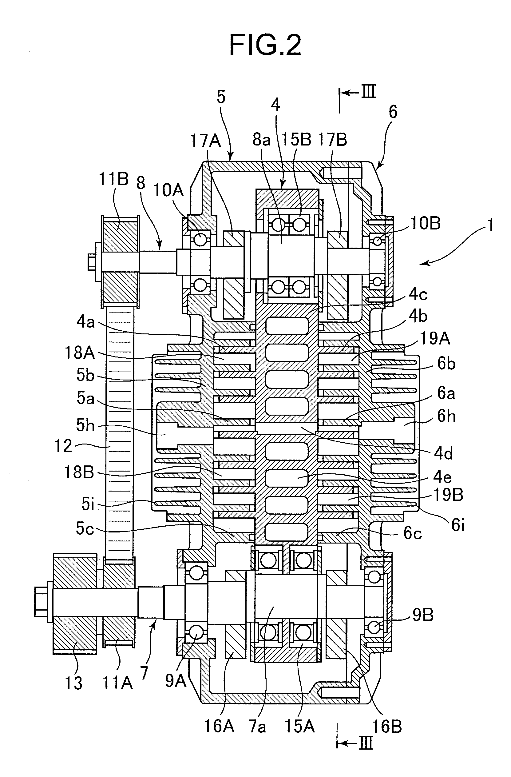
[0026]FIG. 1 is a configuration diagram of a water-injection type scroll air compressor in an embodiment of the present invention, with the compressor body shown in perspective view and both an air line and a water line shown schematically. FIG. 2 is a plan sectional view that shows detailed construction of the compressor body in the embodiment of the present invention, and FIG. 3 is a side sectional view that shows the detailed construction of the compressor body. FIG. 4 is a partially enlarged view that shows compression chambers present inside the compressor body shown in FIG. 3.

[0027]The water-injection type scroll air compressor in FIGS. 1 to 4 includes the compressor body 1 that compresses air, an air suction pipeline 2 provided on a suction (intake) side of the compressor body 1, and an air discharge pipeline 3 provided on a discharge (exhaust) side of the compress...


PUM


Abstract

Disclosed is a water-injection type scroll air compressor whose pre-stopping operation time for drying can be reduced while enhancing compressor efficiency. The compressor body 1 includes a water supply line 24 for supplying water to a water feeder 23 connected to an air suction line 2. The water supply line 24 is provided with a control valve 27 that can control a flow rate of the water. A controller 28 conducts driving control of the control valve 27 in a 5×10⁻⁵ to 40×10−5 range of an injected-water volume ratio (more specifically, a volume ratio between an intake air flow rate and injected-water flow rate in the water feeder 23 of the suction line 2) and at the same time, in an injected-water volume ratio range of the compressor characterized so that an increase rate of overall adiabatic efficiency of the compressor per 1×10⁻⁵ increase rate of the injected-water volume ratio stays less than 2% of an original or initial value.

Description

BACKGROUND OF THE INVENTION[0001]1. Field of the Invention[0002]The present invention relates generally to scroll air compressors that compress air, and more particularly, to a water-injection type scroll air compressor that entrains water in air.[0003]2. Description of the Related Art[0004]In scroll air compressors, an orbiting scroll member with a nearly spiral wrap formed thereon is mechanically oscillated with respect to a fixed scroll member having a nearly spiral wrap formed thereon to mate with the wrap of the orbiting scroll member, and thus, air is compressed by the oscillation. Known examples of these scroll air compressors include an oil-cooled type that entrains an oil in air, and a water injection type that entrains water in air as described in JP-1996-128395-A (FIG. 10), for example. The oil or water entrained in air creates two actions. One seals the slight clearances between the wrap of the orbiting scroll member and that of the fixed scroll member, these wraps formi...

Claims


Application Information

Patent Timeline
Patent Type & Authority Applications(United States)
IPC IPC(8): F01C21/06F01C1/02
CPCF04C18/0223F04C28/06F04C2270/19F04C2240/81F04C29/042F04C18/0253
Inventor KAMEYA, HIROTAKASHIINOKI, KAZUAKIKAWABATA, NATSUKIKOHSOKABE, HIROKATSU
Owner HITACHI IND EQUIP SYST CO LTD
Why Eureka
Try Eureka