Delivery device

a delivery device and fluoride technology, applied in the field of fluoride delivery devices, can solve the problems of difficulty in identifying whether the piston is in the pump, the initial cost of the pump, and the user's difficulty in determining the infusion speed, so as to achieve safe and easy identification and improve safety.

Inactive Publication Date: 2006-03-30
NOVO NORDISK AS
View PDF18 Cites 258 Cited by
  • Summary
  • Abstract
  • Description
  • Claims
  • Application Information

AI Technical Summary

Benefits of technology

[0016] It is a first object of the present invention to provide a fluid delivery device of the type using a flow restrictor in combination with a drive fluid whic

Problems solved by technology

However, the above-described deterioration is reflected in the fact that beta cell stimulators will eventually fail to stimulate the cell, and the patient has to be treated with insulin, either as mono therapy, or in combination with oral medication in order to improve glucose control.
The second mode is infusion pump therapy, which entails the purchase of a relatively expensive pump, for which reason the initial cost of the pump is a barrier to this type of therapy.
Consequently, when it is an object to provide an infusion device which can be manufactured cost-effectively, it would in many cases not be desirable to incorporate expensive components such as electronic control means which in combination with display means could be used to provide the user with informati

Method used


Image

  • Delivery device
  • Delivery device
  • Delivery device

Examples


Embodiment Construction

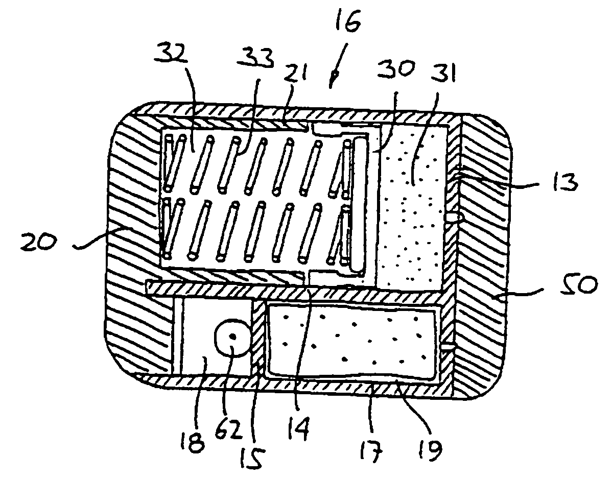
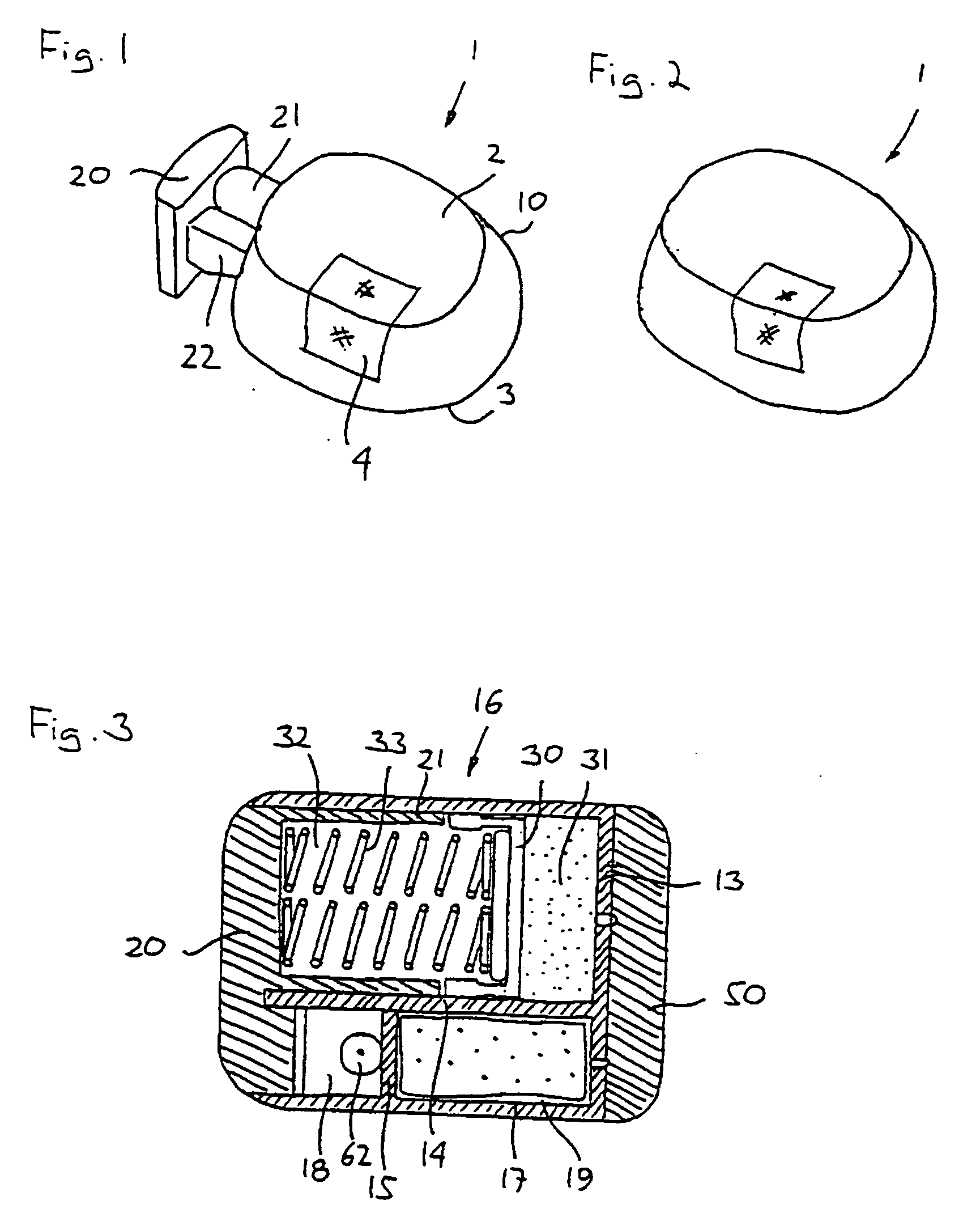
[0082]FIG. 1 shows a schematic representation of an embodiment of the invention. Correspondingly, the configuration of the different structures as well as there relative dimensions are intended to serve illustrative purposes only. This also applies to the other figures. When in the following terms as “upper”, “lower”, “right” and “left” or similar relative expressions are used, these only refer to the appended figures and not to an actual situation of use. In the same way the terms “horizontal” and “vertical” refer to planes parallel with respectively perpendicular to a lower surface of the device to be described. Further, like structures are indicated by like reference numerals.

[0083] More specifically, FIG. 1 shows an infusion device 1 comprising a housing 10 and there from protruding actuation button 20. The housing comprises an upper surface 2 and a lower surface 3 (not to be seen) adapted to be arranged against a skin surface of a user. The upper surface is provided with a tra...


PUM


Abstract

This invention relates to a delivery device of the bleeding hole type, where a primary drive fluid, e.g. silicon oil, is used to expel a secondary fluid, e.g. a drug, contained in a reservoir. To provide a desired drug flow rate, the primary fluid is forced from a first reservoir through a flow restrictor into a second reservoir displacing a portion of the drug reservoir, thereby expelling the drug from its reservoir. The idea is to provide a drive fluid outlet, i.e. a flow restrictor inlet, which protrudes into the first reservoir. By this arrangement the amount of particles and air-bubbles entering the narrow flow restrictor will be reduced. The reduction is achieved because particles and air-bubbles will normally concentrate in the top or bottom of the reservoir, whereas the protrusion will primarily connect to the centre of the first reservoir.

Description

CROSS-REFERENCE TO RELATED PATENT APPLICATIONS [0001] This patent application is a continuation of PCT Patent Application No. DK2004 / 000218, filed Mar. 29, 2004 and claims the benefit of U.S. Provisional Patent Application Nos. 60 / 470,145 filed May 13, 2003, and 60 / 503,699 filed Sep. 17, 2003 and Danish Patent Application Nos. PA 2003 00562 filed Apr. 11, 2003 and PA 2003 01259 filed Sep. 3, 2003, the contents of which are fully incorporated herewith by reference.FIELD OF THE INVENTION [0002] The present invention relates to means providing improved functionality and reliability for a fluid delivery device. Such delivery devices are suitable in particular for in situ administration of a therapeutic drug preparation over a prolonged period of time, however, the delivery devices may also be used in areas such as biochemistry, microbiology and chemical analysis. BACKGROUND OF THE INVENTION [0003] In the disclosure of the present invention reference is mostly made to the treatment of di...

Claims


Application Information

Patent Timeline
IPC IPC(8): A61K9/22
CPCA61K9/0004A61M5/141A61M5/14248A61M5/14526A61M5/1454A61M5/16877A61M2005/14204A61M2005/14252A61M2005/14268A61M2005/14506A61M2005/3123A61M2210/0612
Inventor PEDERSEN, PER ELGAARD
Owner NOVO NORDISK AS
Why Eureka
Try Eureka