Quasi-spherical orbital implant

Active Publication Date: 2006-03-30
OCULO PLASTIK
View PDF16 Cites 9 Cited by
  • Summary
  • Abstract
  • Description
  • Claims
  • Application Information

AI Technical Summary

Benefits of technology

[0013] The anterior portion of the implant has a number of mounds and valleys. The mounds protrude away from the surface of the quasi-spherical implant so as to key with the prosthetic eye and provide impr

Problems solved by technology

The astigmatism makes it more difficult for the

Method used


Image

  • Quasi-spherical orbital implant
  • Quasi-spherical orbital implant
  • Quasi-spherical orbital implant

Examples


Embodiment Construction

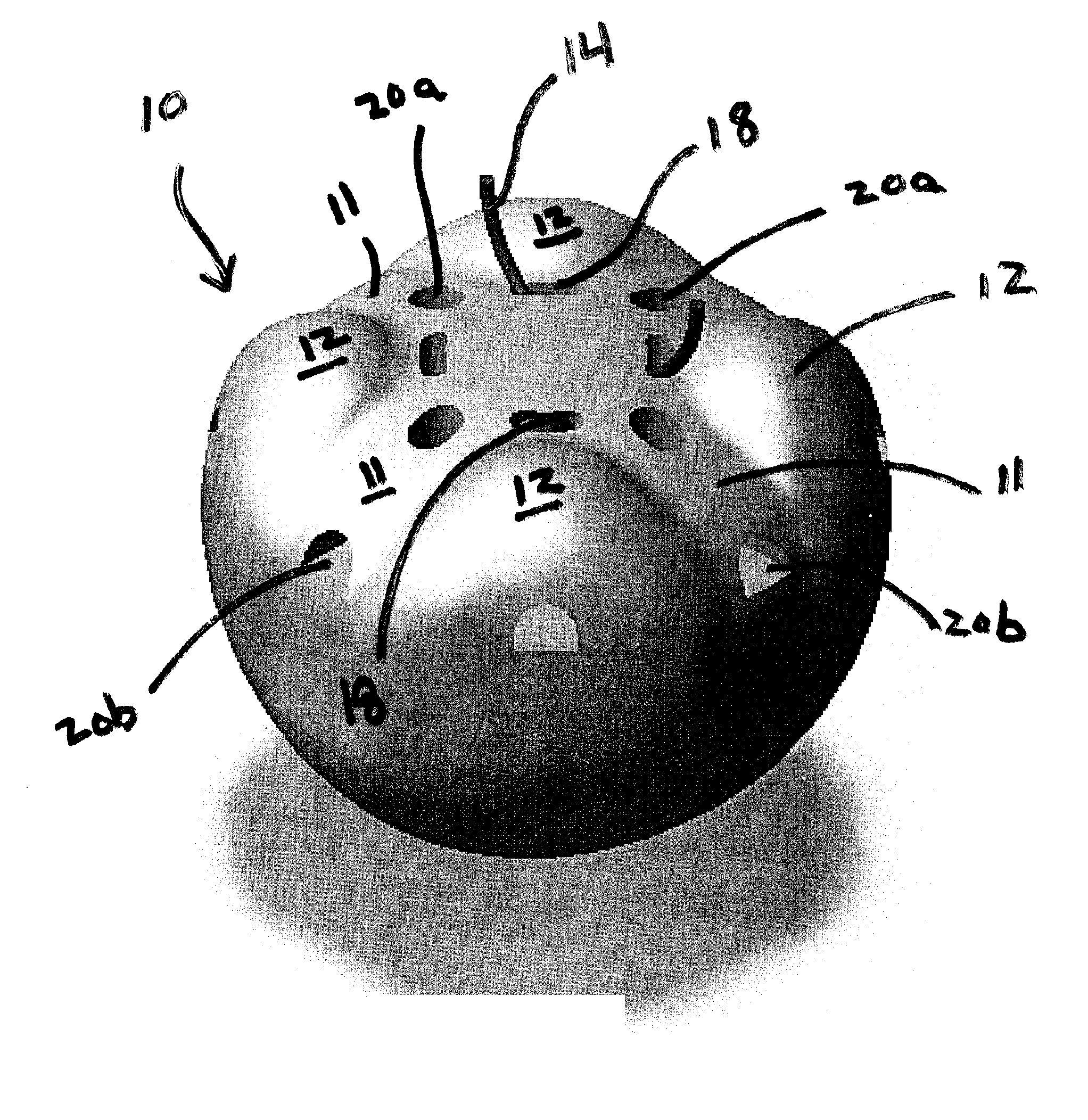
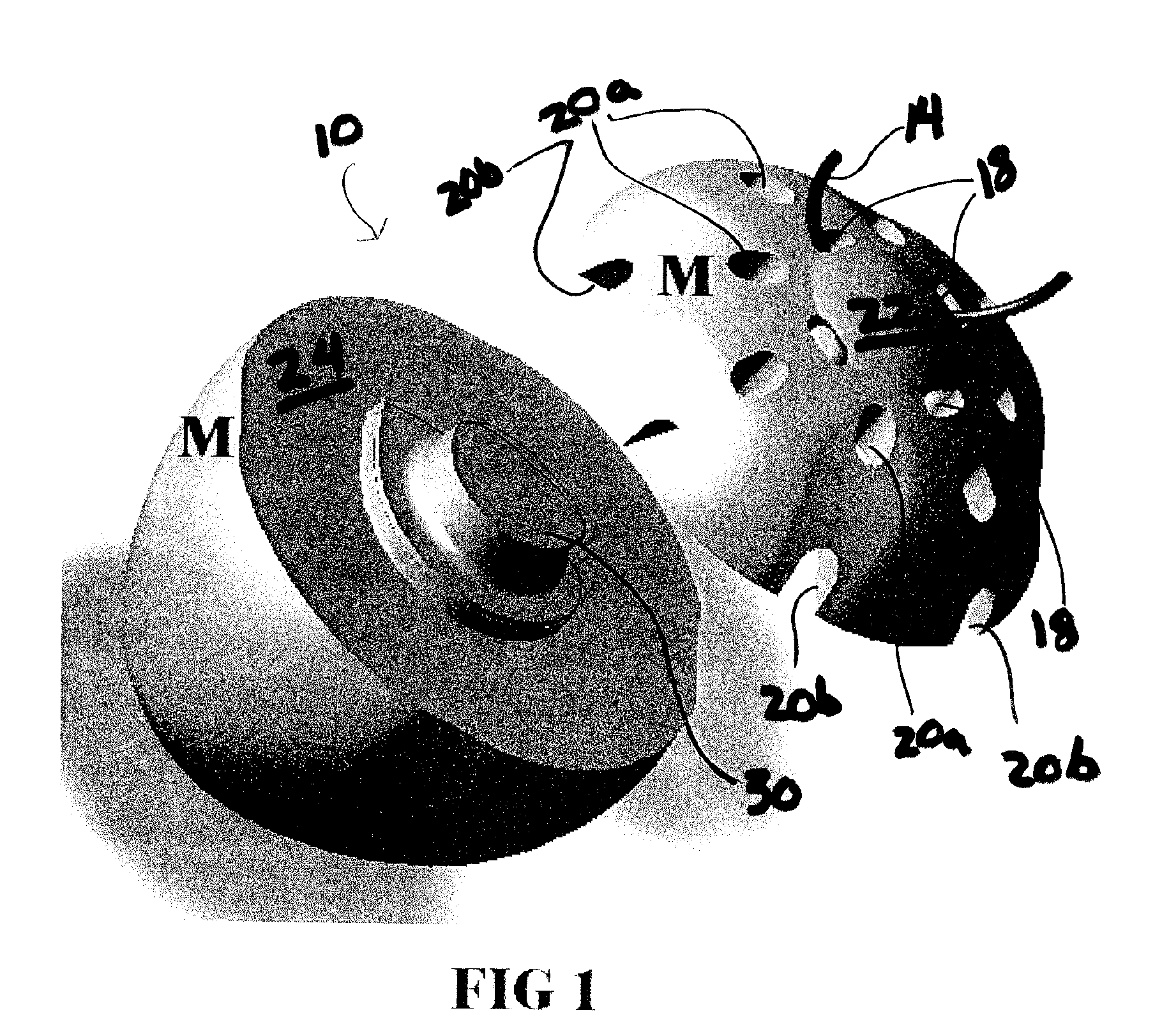
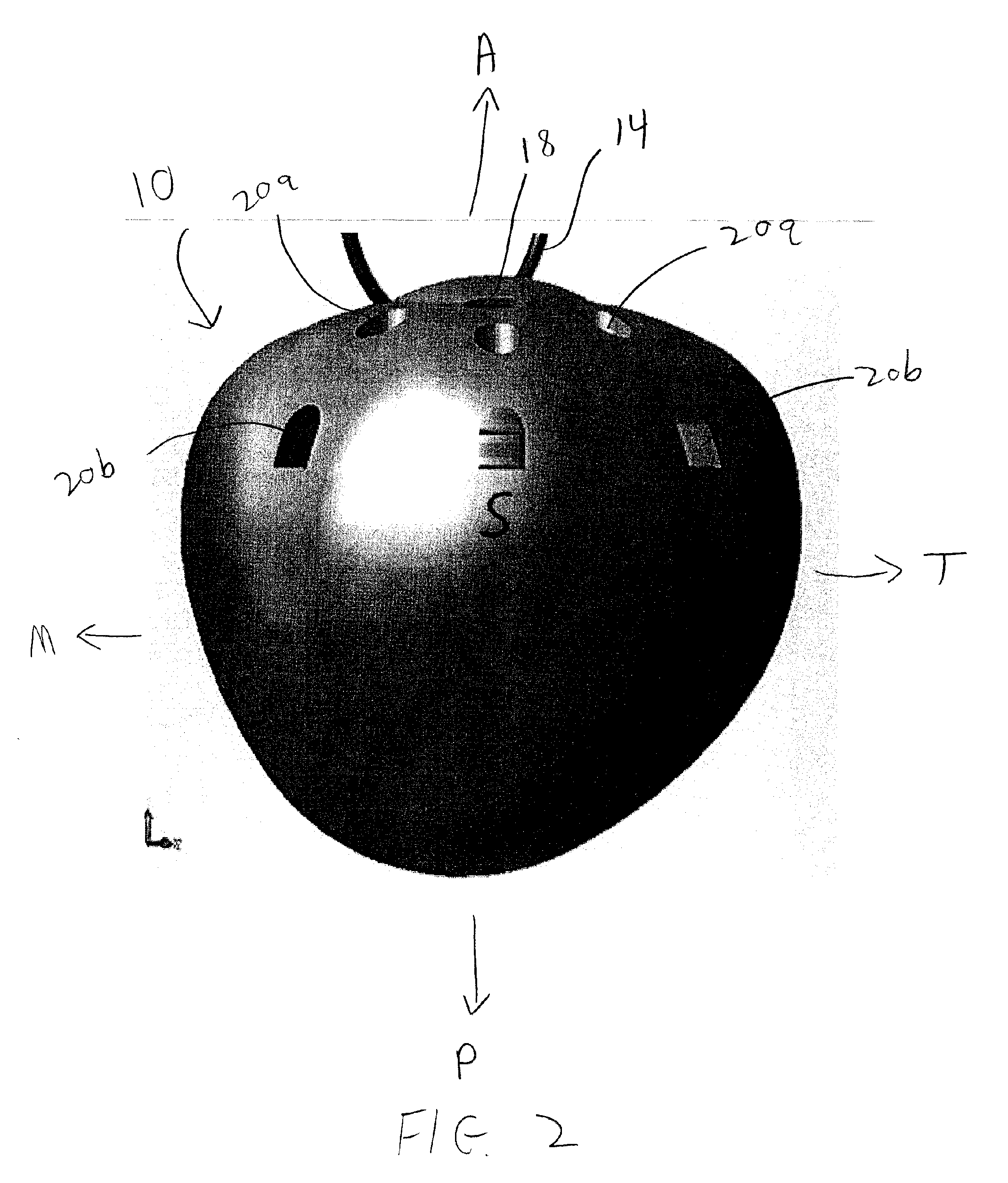
[0032] As seen generally in FIG. 1, the ocular implant 10 of the present invention comprises an anterior portion 22 and a posterior portion 24. Although the implant 10 may be manufactured as one piece, the preferred embodiment requires the implant 10 to be manufactured as two separate pieces. The two pieces 22, 24 will be collectively referred to as the implant 10. As seen in FIG. 3, the anterior portion 22 comprises a finite number tunnels 18, chimneys 20a, 20b, valleys 11, and mounds 12. Cumulatively, the valleys 11 and mounds 12 are herein referred to as details. It should be noted that the terms anterior A, posterior P, medial M, temporal T, superior S, and inferior I all describe the implant 10 as it is properly positioned in a patient's right orbit with the anterior portion 22 facing out of the patient's orbit. These respective directions can be seen in FIGS. 2 and 3. FIG. 2 is a top view of the implant 10 as it sits in a patient's right orbit showing the anterior (front) A, p...


PUM


Abstract

A quasi-spherical orbital implant that comprises an off center conical elongation toward its posterior and medial aspects. The conical elongation mimics the natural shape of an orbit. The implant comprises a number of holes and tunnels for suturing the patient's eye muscles and tissue to the implant. A number of hollow voids in the implant serve to progressively host the formation of tissue which secures the implant to the muscles and covering tissue and helps to prevent migration after the sutures have dissolved. The anterior portion of the implant has a number of details which key with the prosthetic eye and help improve its stability and motility.

Description

BACKGROUND OF THE INVENTION [0001] The invention relates to eye replacement implants. If an eye has become damaged due to trauma or disease, the damaged eye may have to be eviscerated in which all of the inner contents of the eye are removed, or an enucleation may be performed in which the entire eyeball is removed after severing it from the eye muscles and the optic nerve. Following either of these procedures, it is common practice to fill the resulting void with an orbital implant and subsequently fit an ocular prosthesis that closely resembles the eye. After the implant has been inserted into the eye socket following enucleation or evisceration of the eye, tissues heal over the implant. The ocular prosthesis is then placed over these tissues that have healed over the implant. When properly placed within the orbit, the orbital implant replaces some of the volume lost when the eye was removed and helps to maintain the normal structure of the eyelids and eyebrows. When the ocular pr...

Claims


Application Information

Patent Timeline
IPC IPC(8): A61F2/16
CPCA61F2/141
Inventor DURETTE, JEAN- FRANCOIS
Owner OCULO PLASTIK
Why Eureka
Try Eureka