Swirl tube separator

a separator and spiral tube technology, applied in the direction of dispersed particle separation, liquid degasification, separation process, etc., can solve the problem of not being able to separate solids by cyclon

Inactive Publication Date: 2006-04-06
SHELL OIL CO
View PDF22 Cites 36 Cited by
  • Summary
  • Abstract
  • Description
  • Claims
  • Application Information

AI Technical Summary

Problems solved by technology

Such a non-preferred operation results in that the cyclone does not separate solids as optimally as required.

Method used


Image

  • Swirl tube separator
  • Swirl tube separator
  • Swirl tube separator

Examples


Embodiment Construction

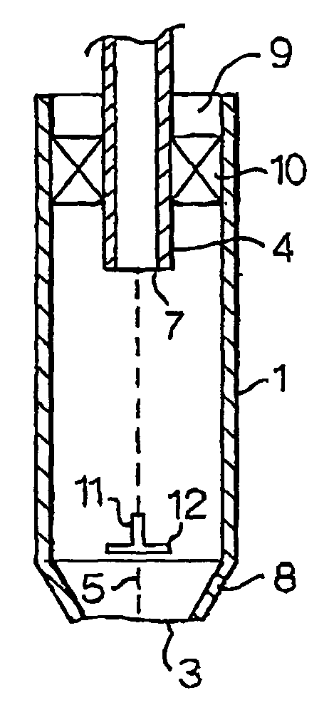
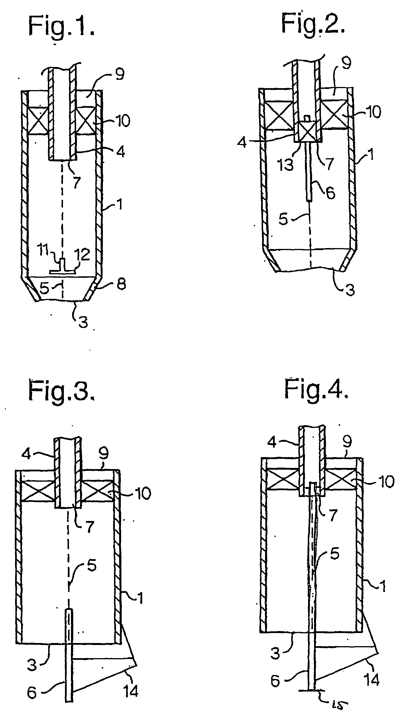
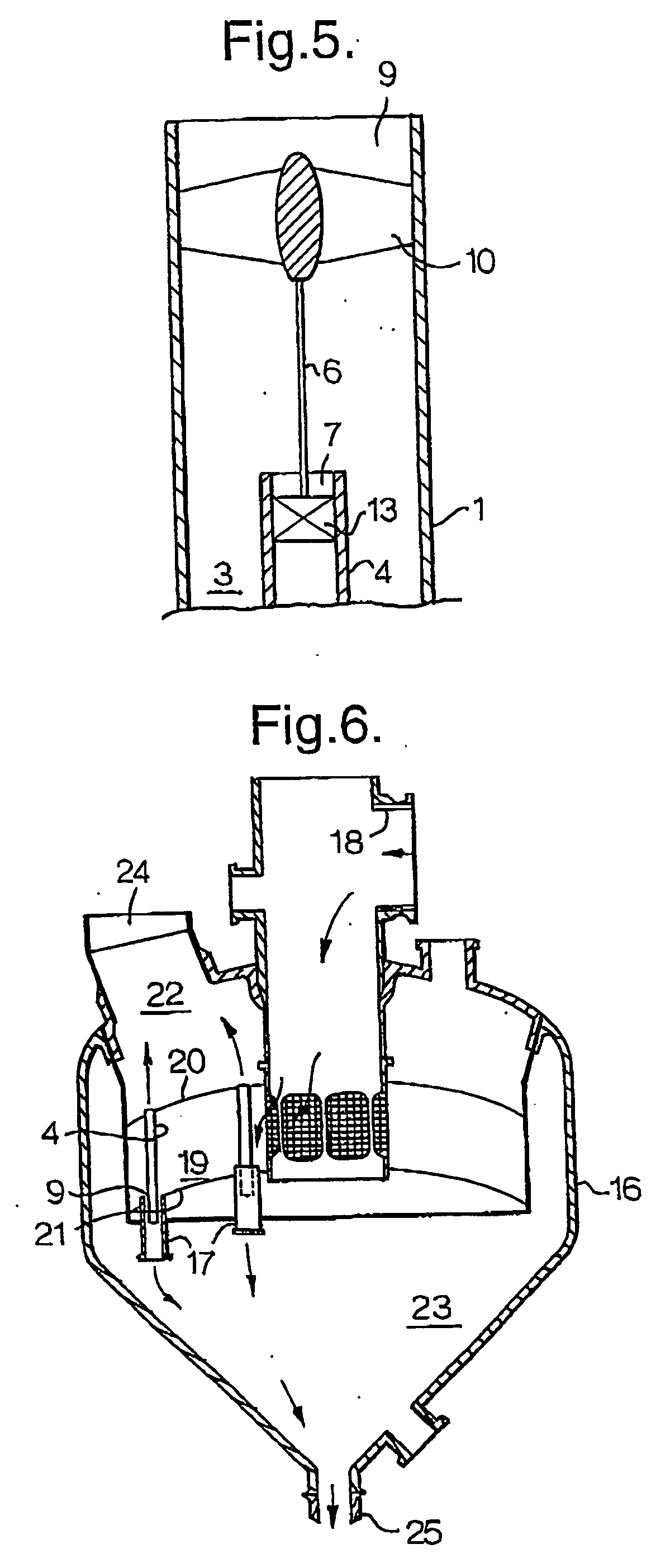
[0014] Applicants found that the above swirl tube separator shows improved separation efficiency in combination with a more stable operation than swirl tube separators not having the above-described pin. This stable operating condition is also observed and advantageous when a multitude of swirl tube separators operate in parallel, wherein the solids outlet opening of each individual swirl tube separators is in fluid communication with the common solids collecting space of the vessel, such as shown in U.S. Pat. No. 5,538,696 and in the above referred to article.

[0015] The actual location of the vortex extender pin along the axis of the tubular housing is not critical as long as the pin runs along a certain length of the axis. Applicants have found that the pin may be located at the solids outlet opening and / or at the gas outlets opening or extend from the gas outlets opening to the solids outlet opening. Thus two separate pins, one extending from the top and one from the bottom and ...


PUM

PropertyMeasurementUnit
diameteraaaaaaaaaa
diameteraaaaaaaaaa
diameteraaaaaaaaaa

Abstract

Swirl tube separator for separating solids from a gas-solid containing feed comprising a tubular housing, an inlet for introducing a gas-solids mixture at one end of said housing, a solids outlet opening at the opposite end of said housing, and a co-axial positioned tubular gas outlet conduit placed at an end of said housing, wherein along the axis of the tubular housing a vortex extender pin is present.

Description

FIELD OF INVENTION [0001] The invention is related to an improved swirl tube separator. The invention is also related to an improved design for a third stage separator comprising the improved swirl tube separators. Such third stage separators may for example be used in a fluid catalyst cracker (FCC) process. BACKGROUND OF INVENTION [0002] The removal of finely-divided solid particles from entraining gases is necessary in almost any system in which the gas is to be passed through a fluid dynamic device containing gas-deflecting walls, such as an expansion turbine at an expander, to prevent erosion damage to such systems. Additionally, if the entraining gas is ultimately to be discharged to the atmosphere, the removal of particulate matter is also important from an environmental conservation standpoint. Emission levels of below 50 mg / Nm3 are sometimes required because of these environmental restrictions. [0003] Suitable separators for removal of finely divided solid particles from ent...

Claims


Application Information

Patent Timeline
Patent Type & Authority Applications(United States)
IPC IPC(8): B01D45/12
CPCB01D45/16
Inventor DEWITZ, THOMAS SHAWNDRIES, HUBERTUS WILHELMUS ALBERTUSEKKER, ANDREASKATER, JANSANBORN, RICHARD ADDISONHOFFMANN, ALEX CHRISTIANPENG, WEIMING
Owner SHELL OIL CO
Why Eureka
Try Eureka