

Pressure actuated tubing safety valve
- Summary
- Abstract
- Description
- Claims
- Application Information
AI Technical Summary
Benefits of technology
Problems solved by technology
Method used
Image

Examples
Embodiment Construction
[0019] The apparatus and methods of the present invention allow for a subsurface safety valve for use in high pressure wells. Embodiments of the present invention provide safety valves that utilize normal wellbore pressure for actuation of the valve, which removes the need for hydraulic systems with control lines extending from the surface to the valve.
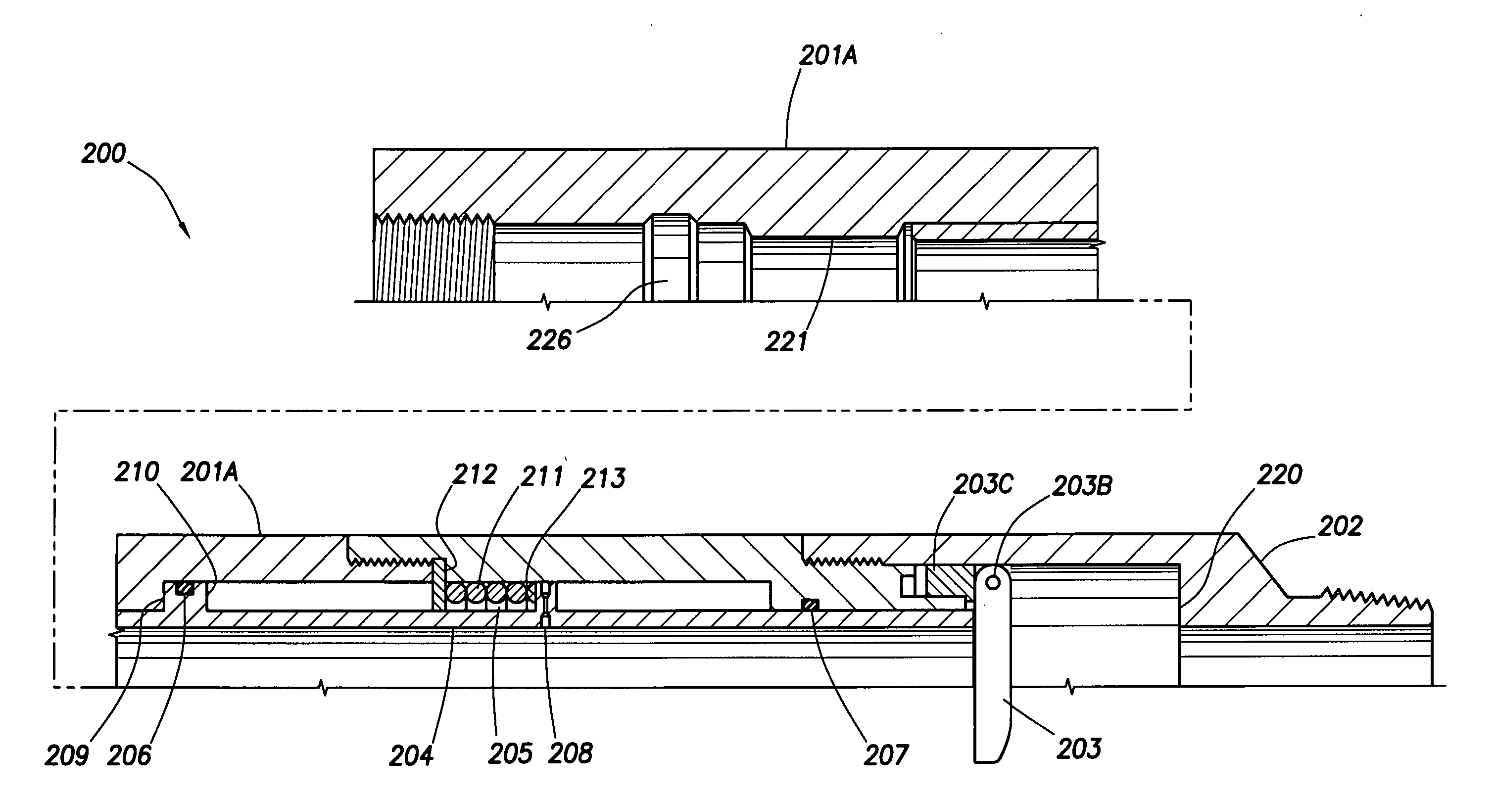
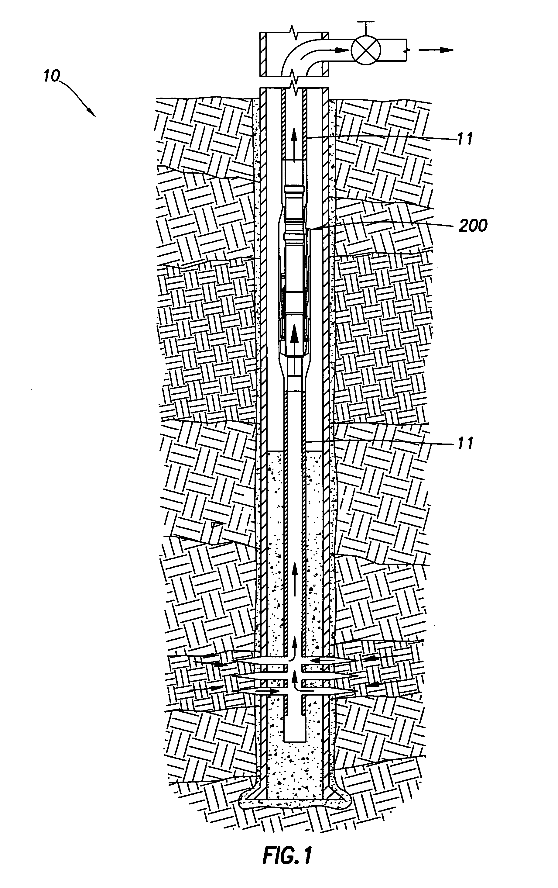
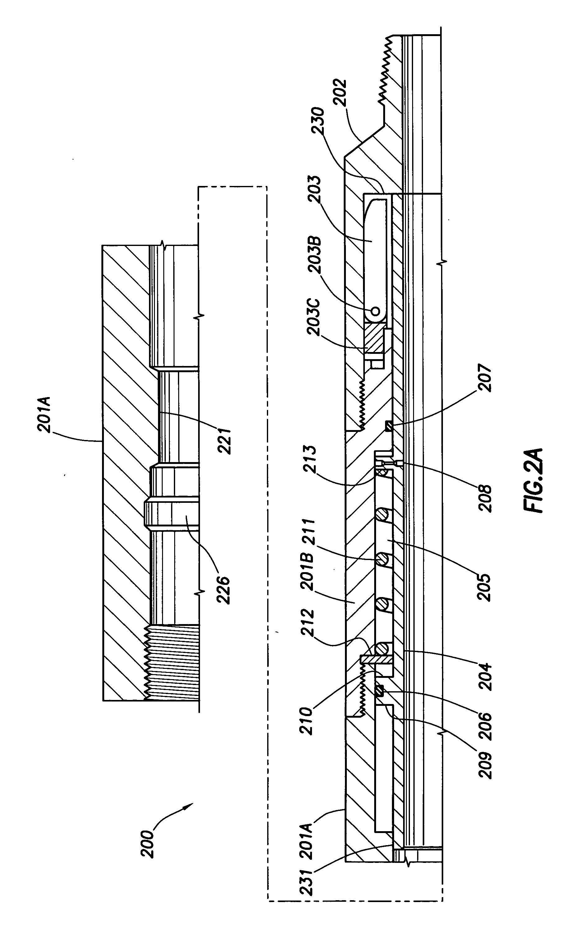
[0020]FIG. 1 is a cross-sectional view of an illustrative wellbore 10. The wellbore is completed with a string of production tubing 11. The production tubing 11 defines an elongated bore through which servicing fluid may be pumped downward and production fluid may be pumped upward. The production tubing 11 includes a safety valve 200 in accordance with one embodiment of the present invention. The safety valve 200 is used for controlling the upward flow of production fluid through the production tubing 11 in the event of a sudden and unexpected pressure loss (also referred to herein as a “pressure drop”) of production fluid may coinci...
PUM
 Abstract
Description
Claims
Application Information