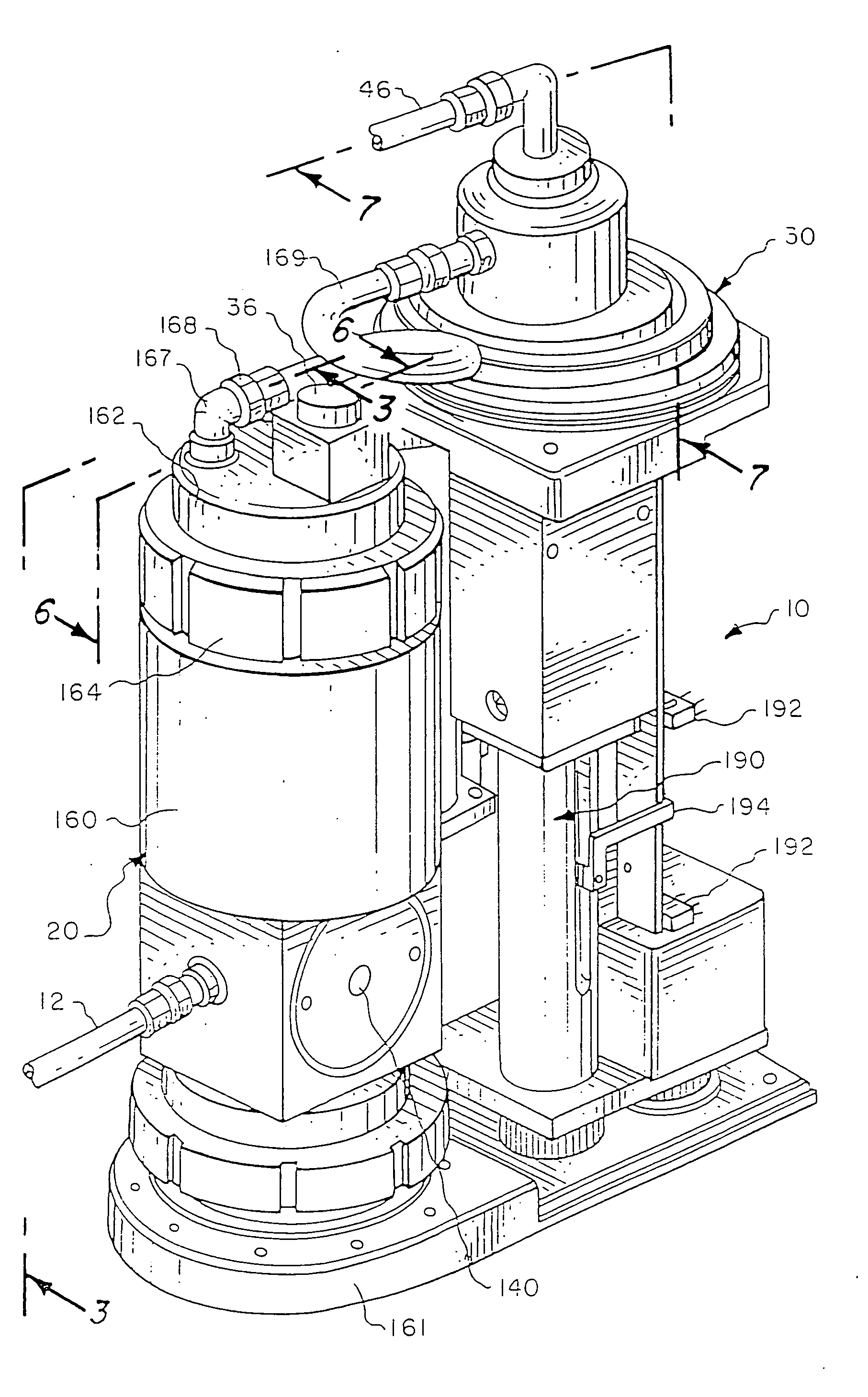
Apparatus and methods for pumping high viscosity fluids

a technology of high viscosity fluids and apparatus, which is applied in the field of apparatus and methods for pumping high viscosity fluids, can solve the problems of unavoidable introduction of small air bubbles, inability to achieve optimal venting, and corresponding undesirable contamination of fluids, so as to facilitate the use of the system, improve performance and benefits, and simplify the flow path

Inactive Publication Date: 2006-04-06
ENTEGRIS INC
View PDF85 Cites 46 Cited by
  • Summary
  • Abstract
  • Description
  • Claims
  • Application Information

AI Technical Summary

Benefits of technology

[0009] It is, therefore, an object of my invention to provide a fluid dispensing system that provides the improved performance and benefits discussed herein. The system is characterized by substantially vertical fluid flow from its inlet to its outlet when the system is in its normally upright position, and by providing Teflon® or similar non-contaminating wetted surfaces throughout the flowpath. In its preferred embodiment, the flow path is simplified as compared to prior art systems, including fewer fittings and connections (in part resulting from integrally forming various components into single unitary structures).
[0010] A further object of the invention is the provision of a device for processing fluid in a precisely controlled manner, including the combination of first pumping means and second pumping means in fluid communication with each other, in which the fluid travel path that is substantially consistently upward as the fluid flows through the first pumping means and the second pumping means. As indicated above, the first and second pumping means surfaces that contact the fluid are preferably all fabricated from or coated with a relatively non-contaminating material, such as Teflon® or the like. Among other things, this facilitates using the system for high-purity fluids, in cleanroom environments, etc.
[0011] The device can further include filter means between the first pumping means and the second pumping means, in which case the fluid travel path preferably remains substantially consistently upward as the fluid flows through the first pumping means, the filter means, and the second pumping means, and all or substantially all contacting surfaces are non-contaminating. In the preferred embodiment, the pump head and the valve therein are actually fabricated from Teflon®, and all fittings along the flow path are flare fittings formed from Teflon® or otherwise having wetted surfaces that are non-contaminating to the subject fluid. For the non-contaminating aspect of the invention, the particular material may be any suitable non-contaminating material, including without limitation various forms of Teflon® (TFE & PFA), Kalrez (a fluorinated, Teflon®-like elastomer), or other materials. Among the many suitable fittings usable in the invention, commercially available Furon Flare Grip® PFA tube fittings can be readily utilized.
[0012] Another object of the invention is the provision of a system or device of the aforementioned character, in which the first pumping means includes an upper head portion removable from a lower portion, and means are provided for temporarily attaching the upper head portion to a lower portion to form a pumping chamber therebetween. Preferably, the upper head portion includes integrally formed valve means configured to thereafter direct the process fluid in a substantially upward path toward a filter chamber integrally formed in the upper head portion. Among other things, the integral valve facilitates filtering viscous and other fluids under relatively low pressure, and decreases molecular shear on the fluids, in part by providing relatively larger and less obstructed flow paths through the valve (as compared to prior art systems). The valve also reduces differential pressure, or pressure drop, as the fluids move through the valve.
[0013] An additional object of the invention is the provision of a system or device of the aforementioned character, in which the second pumping means includes an upper head portion removable from a lower portion, with means for temporarily attaching the upper head portion to the lower portion to form a pumping chamber therebetween. Again preferably, the upper head portion of the second pumping means includes an integrally formed tee fluid flowpath therein, wherein the tee provides a substantially direct upward flowpath for the subject fluid from the pumping chamber toward a dispense from the upper head portion. The preferred tee includes an input portion for receiving the subject fluid after it has been pumped by the first pumping means, and the dispense from the second pump's upper head portion is positioned higher than the input portion when the device is in its normal, upright orientation.
[0014] A further object of the invention is the provision of a system or device of the aforementioned character, in which the second pumping means is positioned generally above the first pumping means, and the fluid travel path from an exit of the first pumping means to an inlet into the second pumping means does not include any downwardly directed portions when the device is in its normal, upright orientation.

Problems solved by technology

In certain applications, that path does not afford optimal venting for any contaminating air bubbles that may become entrapped in the fluid or the system.
For example, some small amount of air bubbles may be unavoidably introduced when the source fluid container is periodically changed, even if no re-priming is required.
Portions of the flow path that are metal or otherwise relatively potentially contaminating result in some risk (however small) of corresponding undesirable contamination of the fluid.
As indicated in those prior patents, such bubbles or contaminants could potentially compromise the end product to some degree in some small percentage of applications.
Alternatively, such bubbles or contaminants might require some period of “flushing” bubbles from the system upon changing the source fluid container, for example, or might otherwise compromise the accuracy of the fluid dispense system (again, in a small percentage of applications and situations).
Additionally, reducing and realigning the fluid flow path can reduce the size of the “footprint” for the housing of the system and otherwise make the system more compact as compared to prior art systems, thereby correspondingly reducing valuable factory space for the users of the pump system.

Method used


Image

  • Apparatus and methods for pumping high viscosity fluids
  • Apparatus and methods for pumping high viscosity fluids
  • Apparatus and methods for pumping high viscosity fluids

Examples


Embodiment Construction

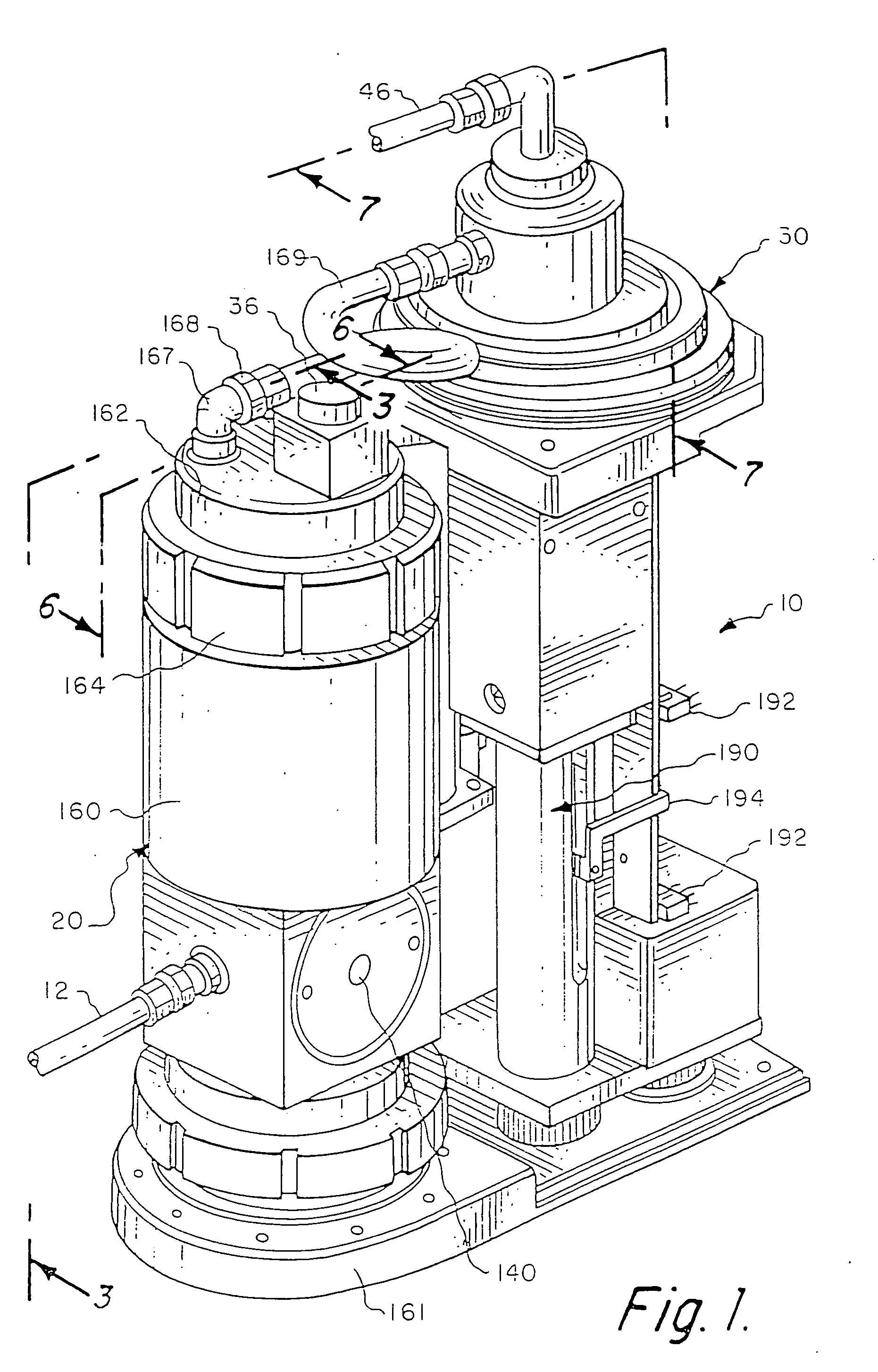
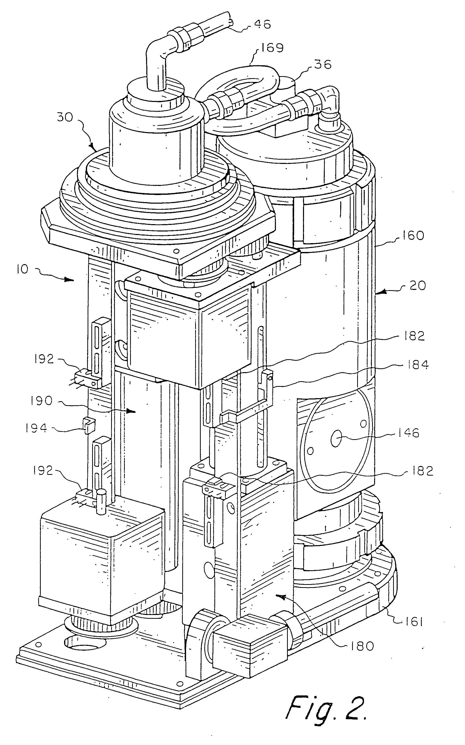
[0040] Referring now to the drawings, and particularly FIGS. 1 and 2, I show a preferred embodiment of a pump and dispense system 10 constructed in accordance with the teachings of the invention. Preferably, the system includes a first pumping means or master pump 20, and a second pumping means or slave pump 30, operably connected to pump fluid from an inlet 12 to an outlet 46. As described herein, filtering means can be included between the master and slave pumps 20 and 30, or preferably within the master pump 20 (as described herein), to filter the process fluid.

[0041] General concepts regarding the components and operation of the preferred system and its pump mechanisms are disclosed in U.S. Pat. Nos. 5,167,837, 5,516,429, and 5,772,899, which are hereby incorporated herein by reference. An overview of a preferred method of operation of the present invention is illustrated in FIG. 8. Fluid taken from an initial fluid source 60 (FIG. 8) is drawn into the system 10 through the inl...


PUM

PropertyMeasurementUnit
sizeaaaaaaaaaa
purityaaaaaaaaaa
pressureaaaaaaaaaa

Abstract

A system for dispensing and filtering fluid is disclosed, in which the fluid flow path is substantially vertical from the fluid inlet through fluid dispense. Substantially all wetted surfaces are Teflon® or some similar non-contaminating fluid, for applications such as cleanroom processes. A valve and a filter chamber are incorporated into a pump head to simplify the flow path and reduce potential contamination points. Preferred methods, and chips or other microelectronic devices fabricated from the apparatus or methods, are also disclosed.

Description

[0001] The present invention relates to pumps for precisely dispensing fluids and methods related thereto, as well as various products made by those pumps and methods. BACKGROUND OF THE INVENTION [0002] This invention relates to a pumping system useful in dispensing fluids, especially those that are expensive, viscous, high purity, and / or sensitive to molecular shear. The invention also relates to microelectronic components such as silicon chips and wafers, microelectronic substrates, and circuits fabricated by such pumping systems and methods, including the potentially improved quality and yield of such products achievable with the invention as compared to prior art systems. [0003] General aspects of the relevant background of the invention are discussed in prior U.S. Pat. Nos. 5,167,837; 5,772,899; and 5,516,429. Among other things, the invention has numerous applications, but is especially useful in the microelectronics industry. The trend in that industry continues to be to sque...

Claims


Application Information

Patent Timeline
Patent Type & Authority Applications(United States)
IPC IPC(8): B01D37/00F04B41/06B67D7/58B01D35/26B01J4/02F04B13/00F04B23/06F04B43/02F04B43/06F04B43/067F04B53/14F04B53/20
CPCB01D35/26B01D37/00F04B43/02F04B43/06F04B43/067F04B53/20F05C2225/04F04D7/04
Inventor GIBSON, GREGORY M.
Owner ENTEGRIS INC
Why Eureka
Try Eureka