Conveying roller, production method thereof and conveying apparatus

a technology of conveying roller and production method, which is applied in the direction of thin material handling, web handling, article separation, etc., can solve the problems of generating the skew deteriorating the quality of edge portions of photosensitive recording paper, so as to prevent the slipping of an elastic layer and prevent the effect of conveying failures

Inactive Publication Date: 2006-04-06
FUJIFILM CORP
View PDF4 Cites 21 Cited by
  • Summary
  • Abstract
  • Description
  • Claims
  • Application Information

AI Technical Summary

Benefits of technology

[0012] An object of the present invention is to provide a conveying roller, a production method thereof and a conveying apparatu

Problems solved by technology

As a result, the quality in edge portions of the photosensitive recording paper may be deteriorated.
Accordingly, a conveying force becomes unbalanced in the width direction so that the photosensitive recording paper may be skewed.
As a result, contact condition and contact pressure between the photosensitive recording paper and the projections of the projection roller vary in the width direction, which may generate the skew of the photosensitive recording paper.
In particular, since the projection roller is soaked in the processing solution for a long time, the projection tube is swelled to a certain extent even if the projection tube is formed of a chemical-resistant material.
Especially in the developing solution, the problems such as the slipping of the projection tube and failures in conveying the photosensitive recording paper tend to increase as the tightening force of the projection tube is down by the swelling.
As a result, the stress applied to the projections during the conveyance accelerates the expansion of the projection tube which causes stress relaxation.
Inserting the core into the projection tube is troublesome since the core should be inserted while expanding the projection tube.
Further, when inserting the core into the projection tube, there may be a gap between the core and the projection tube, or a distortion on the projection tube.
Furthe

Method used


Image

  • Conveying roller, production method thereof and conveying apparatus
  • Conveying roller, production method thereof and conveying apparatus
  • Conveying roller, production method thereof and conveying apparatus

Examples


Embodiment Construction

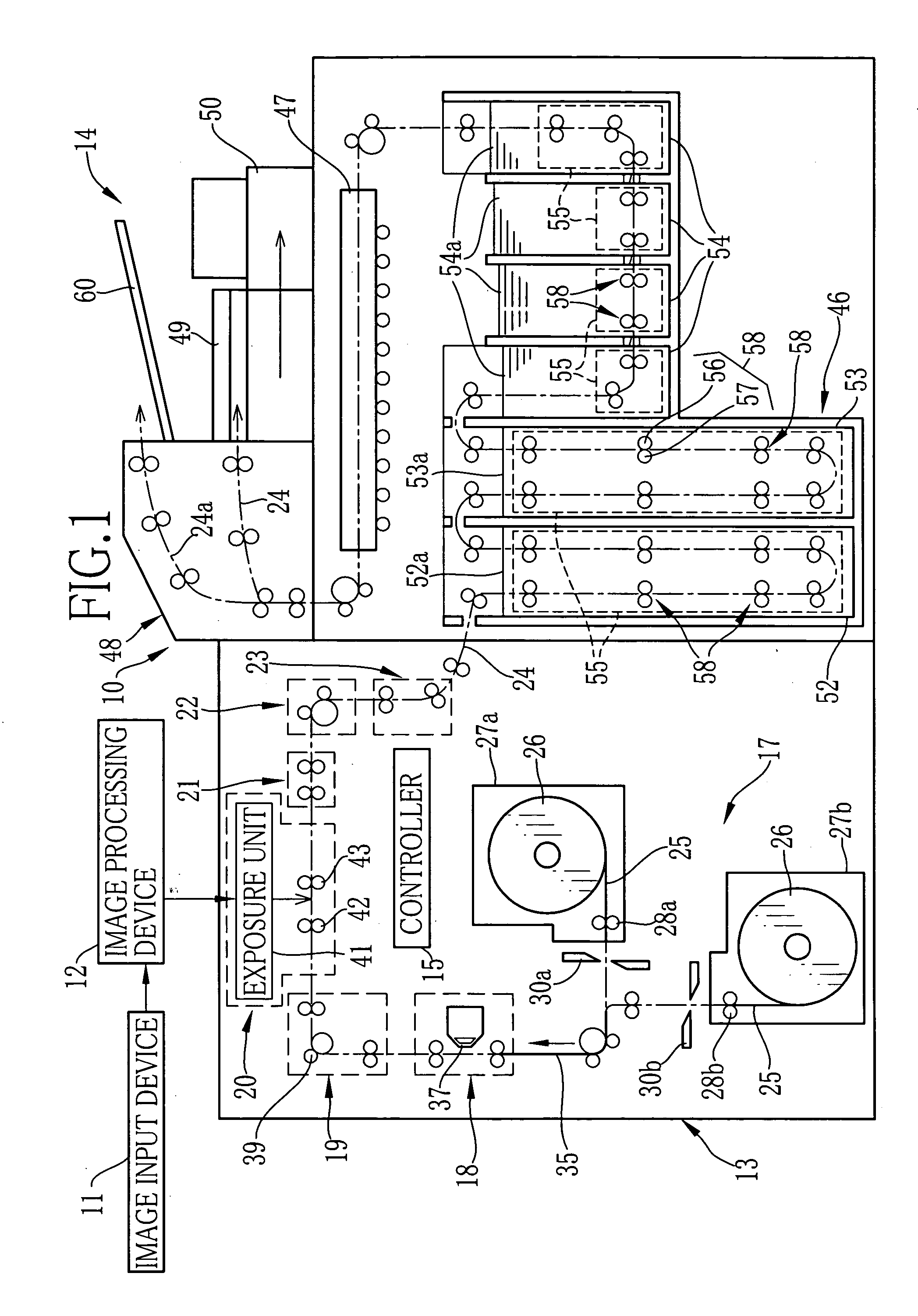
[0035] As shown in FIG. 1, a photographic printing system 10 is an image output apparatus which is constituted of an image input device 11, an image processing device 12, a printer 13, a processor 14 and the like. Each section of the photographic system 10 is connected to a controller 15 through wiring (not shown). The controller 15 controls the overall operation of the photographic system 10.

[0036] The image input device 11 generates image data by photoelectrically reading an image recorded on a photographic film by using an image capture device such as a CCD image sensor, or obtains the image data by reading the image data recorded in a recording medium such as a memory card, CDR, DVD-R and the like. The image data is sent to the image processing device 12, and image processing such as color balance correction and density correction are performed to the image data. After the image processing, the image data is sent to the printer 13.

[0037] The printer 13 records images on a phot...


PUM


Abstract

A conveying roller pair disposed in a bleaching-fixing bath of a photographic printer is constituted of a flat roller and a projection roller. Plural roller pieces are fixed to a roller shaft of the projection roller. Plural projections are formed by coating molding on an outer peripheral surface of the roller piece. Each roller piece has a core with an approximately ring shape, and an elastic layer with plural projections. The core and the elastic layer are adhered through a primer layer. Accordingly, uniform adhesive strength is secured and slipping of the elastic layer on the core is prevented. Since the plural projections are arranged in a phase-coherent manner, contact condition and contact pressure between the sheet and the projection roller are kept constant. As a result, a skew of the sheet is prevented.

Description

BACKGROUND OF THE INVENTION [0001] 1. Field of the Invention [0002] The present invention relates to a conveying roller having plural projections on an outer peripheral surface thereof, a method for producing the conveying roller and a conveying apparatus using the conveying roller. [0003] 2. Background Arts [0004] For example, a photographic printer performs processes of exposing, developing, drying and the like in this order to a photosensitive recording paper of a cut-sheet type while conveying in a sub-scanning direction. The photosensitive recording paper is nipped and conveyed by a plurality of conveying roller pairs disposed along a passage. Because of the restrictions such as a printer size and the like, the passage is curved in up-and-down directions in several sections in the printer, particularly in a processing tank in which a processing solution for developing is stored. For that reason, the plurality of conveying roller pairs are placed in the processing tank at narrow...

Claims


Application Information

Patent Timeline
IPC IPC(8): B65H5/02B65H5/04B65H29/20
CPCB65H27/00B65H2404/133B65H2404/521B65H2404/5521B65H2404/563
Inventor ITOH, KOJI
Owner FUJIFILM CORP
Why Eureka
Try Eureka