Instantaneous phase digitizer
a digital converter and phase digitizer technology, applied in the field of analog to digital conversion, can solve the problem of frequency generated by the loop slipping away without repeated corrections
- Summary
- Abstract
- Description
- Claims
- Application Information
AI Technical Summary
Problems solved by technology
Method used
Image
Examples
Embodiment Construction
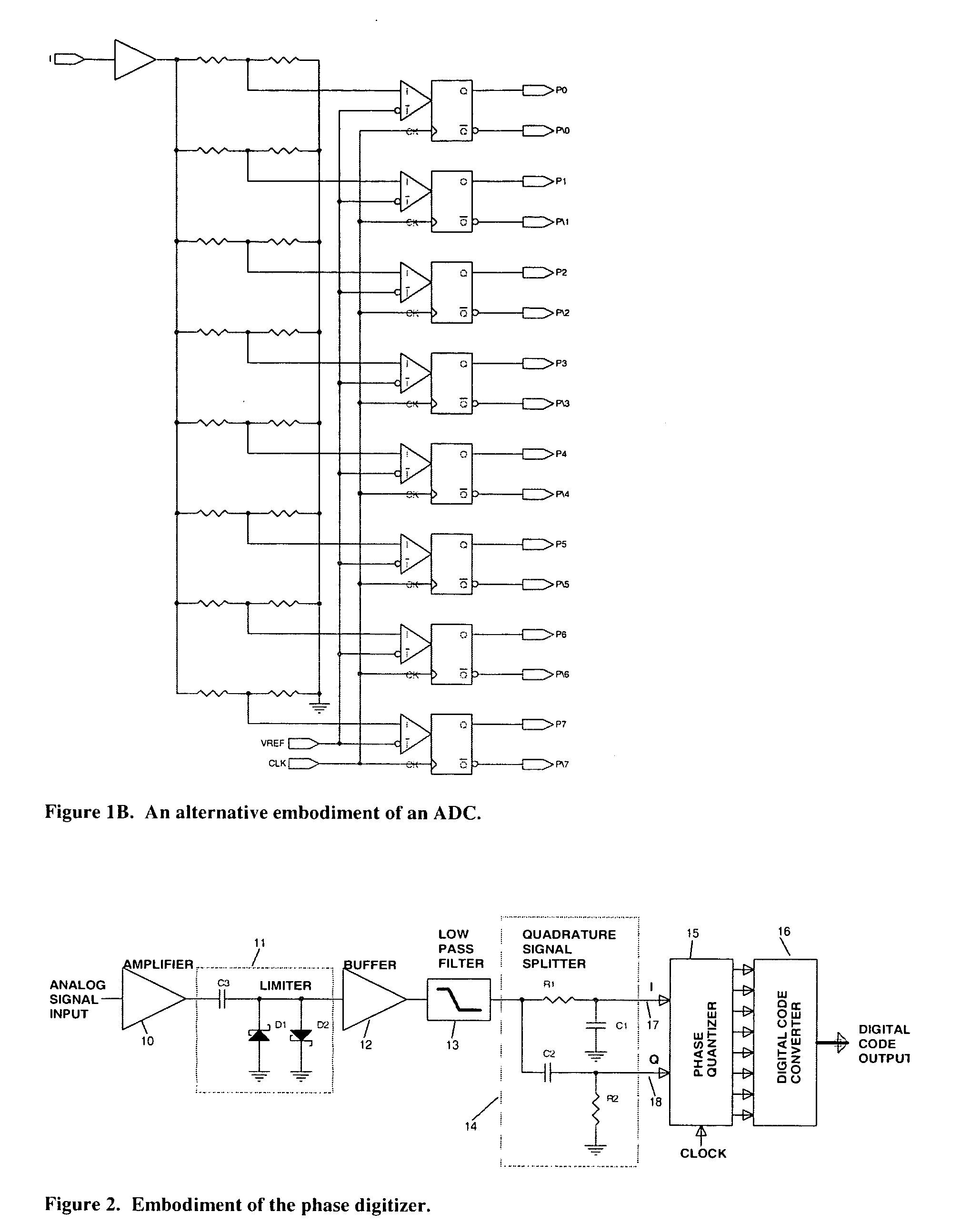
[0043] In the embodiment shown in FIG. 2, the input signal, is amplified by the high gain amplifier (10), and then applied to a limiter (11), which in this embodiment is comprised of two Schottky diodes (D1, D2). As a result, the combination of the amplifier followed by the limiter produces a nearly ideal rectangular waveform.
[0044] The limiter is followed by a buffer (12), and than a low-pass filter (13). The filter (13) defines the operational frequency range of the digitizer, and It is designed such that its cutoff frequency Fco is lower than half the sampling clock frequency Fck.
[0045] The filter is followed by a quadrature signal splitter (14), comprised of resistors R1, R2, and capacitors C1, C2, wherein R1=R2=R, and C1=C2=C. The values of R and C, are selected such that at the frequency in the middle of the operational band of the digitizer, Fmid=Fco / 2, R=2ΠFmidC. As a result, the phases of the signal coming out of the splitter are shifted. By the combination of R1, and C1,...
PUM
 Abstract
Description
Claims
Application Information
 - R&D
- Intellectual Property
- Life Sciences
- Materials
- Tech Scout
- Unparalleled Data Quality
- Higher Quality Content
- 60% Fewer Hallucinations
Browse by: Latest US Patents, China's latest patents, Technical Efficacy Thesaurus, Application Domain, Technology Topic, Popular Technical Reports.
© 2025 PatSnap. All rights reserved.Legal|Privacy policy|Modern Slavery Act Transparency Statement|Sitemap|About US| Contact US: help@patsnap.com


