Power grid frequency measurement method and device

A technology of power grid frequency and measurement method, which is applied in the field of electric power, can solve the problems of long measurement time and poor precision, and achieve the effect of improving accuracy, reliability and accuracy, and accurate frequency calculation

Inactive Publication Date: 2011-07-06
SHENZHEN RENERGY TECH
View PDF6 Cites 39 Cited by
  • Summary
  • Abstract
  • Description
  • Claims
  • Application Information

AI Technical Summary

Problems solved by technology

[0004] The embodiment of the present invention provides a grid frequency measurement method, which aims to solve the problems of poor accuracy and long measurement time when measuring the grid frequency in the existing frequency measurement method

Method used


Image

  • Power grid frequency measurement method and device
  • Power grid frequency measurement method and device
  • Power grid frequency measurement method and device

Examples


Embodiment 1

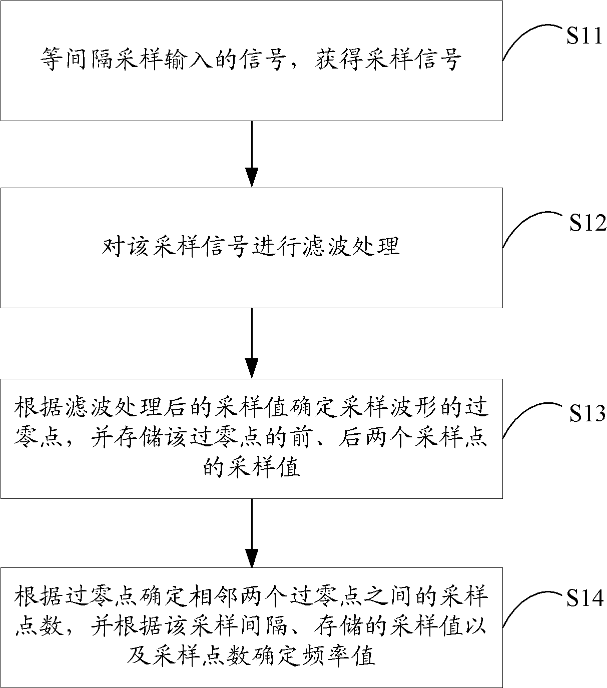
[0039] figure 1 The flow of the grid frequency measurement method provided by the first embodiment of the present invention is shown, wherein the embodiment of the present invention mainly takes the measurement of the fundamental frequency as an example, and the details are as follows:

[0040] In step S11, the input signal is sampled at equal intervals to obtain a sampled signal.

[0041] In the embodiment of the present invention, the input signal is sampled at equal intervals so that the intervals between any two adjacent sampling points are equal to ensure that the sampling frequency of the signal is fixed.

[0042] In step S12, filter processing is performed on the sampled signal.

[0043] In the embodiment of the present invention, before measuring frequencies, it is necessary to filter out signals corresponding to frequencies that do not need to be measured. If you measure the frequency of the 50Hz or 60Hz fundamental signal, you can use a digital low-pass filter to f...

Embodiment 2

[0056] Figure 7 The structure of the power grid frequency measurement device provided by the second embodiment of the present invention is shown, and for the convenience of description, only the parts related to the embodiment of the present invention are shown.

[0057] The power grid frequency measurement device can be a software unit, a hardware unit or a combination of software and hardware running in the terminal, or it can be integrated into these terminals as an independent pendant or run in the application system of these terminals, wherein:

[0058] The sampling circuit 71 is configured to sample input signals at equal intervals to obtain sampling signals with equal sampling intervals.

[0059] In the embodiment of the present invention, the input signal is sampled at equal intervals, so that the intervals between any two adjacent sampling points are equal to ensure that the sampling frequency of the signal is fixed.

[0060] The sampling signal filtering unit 72 is...


PUM


Abstract

The invention is applicable to the power field and provides a power grid frequency measurement method and a device. The method comprises the following steps: sampling inputted signals at equal intervals and obtaining sampled signals with equal sampling intervals; carrying out filtering treatment on the sampled signals; determining a zero crossing point of a sampled waveform according to the sampling value after the filtering treatment and storing the sampling values of front and rear sampling points of the zero crossing point; determining the number of sampling points between the adjacent zero crossing points and measuring the frequency value according to the sampling intervals, the sampling values and the sampling points. As the high-frequency filtering treatment is carried out before the base wave frequency measurement, the embodiment of the invention can effectively eliminate the interference of harmonic waves in the practical power network operation, thereby improving the detection accuracy of the zero crossing point and further improving the reliability and the accuracy of the base wave frequency measurement.

Description

technical field [0001] The invention belongs to the field of electric power, in particular to a method and device for measuring grid frequency. Background technique [0002] In power quality analysis, it is often necessary to measure the frequency and its deviation of the power system. [0003] In the existing fundamental frequency measurement method, the whole cycle sampling point counting method is often used. The method firstly determines the period of the fundamental wave, and then determines the frequency of the fundamental wave according to the time interval between sampling points within the period of the fundamental wave after determining the period of the fundamental wave. When the sampling period is short, the accuracy of the measured frequency is very poor, and when the sampling period is long, it cannot meet the real-time requirements. In addition, this method does not filter out the high-frequency harmonic signal when measuring the frequency. When the harmonic...

Claims


Application Information

Patent Timeline
Patent Type & Authority Applications(China)
IPC IPC(8): G01R23/02
Inventor 苗书立赵文静
Owner SHENZHEN RENERGY TECH
Why Eureka
Try Eureka