
Surveillance system using pulse-coded rays

Inactive Publication Date: 2006-04-06
UNTERHALTUNGSSOFTWARE SELBSTKONTROLLE
View PDF3 Cites 19 Cited by
  • Summary
  • Abstract
  • Description
  • Claims
  • Application Information

AI Technical Summary

Benefits of technology

[0019] In this way, it is possible to prevent interference, caused by using the same identifying signal in duplication, by using pulse codes, which are different, in all the photosensors respectively. In addition, since being outputted in a short time of 450 μs (it is preferable that it is 500 μs or less) within a period of, for example, 20 ms which is a detection period, a pulse coded ray in conformity with the start-stop system has an advantage that influence to the identification and judgment of a signal also becomes very small since a probability that extraneous light and noise enter in transmitted and received light in comparison with that of the former becomes small.
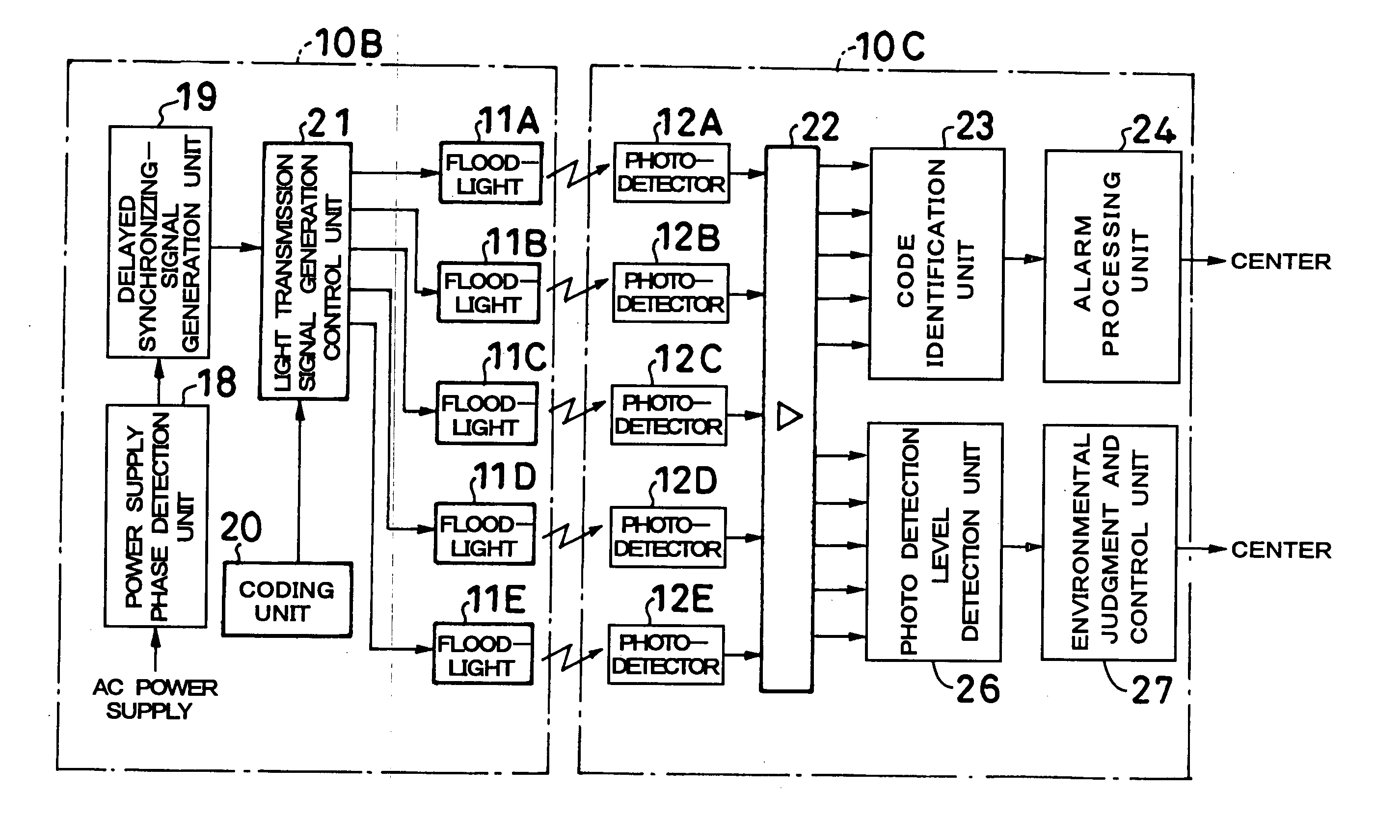
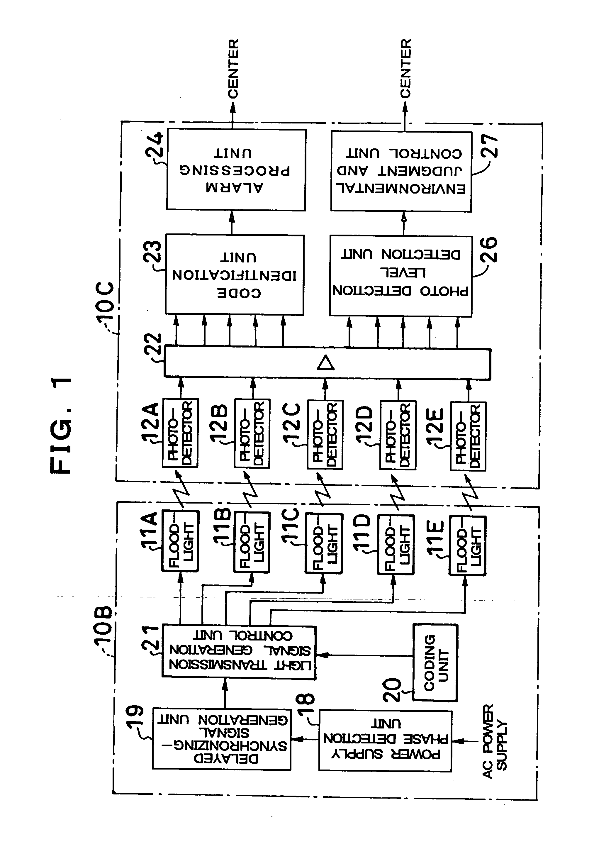
[0020] In addition, a plurality of pulse-coded rays transmitted and received between eight main bodies are transmitted and received serially with a predetermined delay time within the period of, for example, 20 ms by a delayed synchronizing-signal synchronizing with a phase of an AC line. Hence, it is possible to eliminate a malfunction of affecting detection because other light which is not an object of transmission and reception enters into a photosensor as an extraneous light noise.
[0021] Furthermore, by reporting that a photosensor is in a high-level environment when luminance to the photosensor becomes higher than a predetermined high level, and reporting that the photosensor is in a low level environment when becoming lower than a predetermined low level on the other hand, it is possible to prevent an output such as a false alarm caused by an environmental change.

Problems solved by technology

Hence, the existence of an intruder H1 is not detected, and therefore, an alarm failure (an alarm is not given in spite of an intruder entering) arises.
Nevertheless, a conventional pulse count system has a problem that a false alarm (an alarm is given in spite of no intruder) and an alarm failure arises since a number of pulses which is counted is affected by sunlight which is extraneous light, direct projection of vehicle headlight etc., reflection of these extraneous light from an object, or reflection, wraparounds, and interference (noise) of infrared rays used for transmission and reception.
Hence, these lead to false alarms.
Hence, this causes a false alarm or alarm failure.
Hence, there is a problem that it is not possible to perform effective detection since there are few identifiable signals.
Accordingly, when an infrared ray of the signal 1P of the main body Q1 reaches a photodetector unit of the main body Q5 by a wraparound etc., this leads to an alarm failure.
However, even if an infrared optical axis is turned in this way, it becomes hard to prevent the influence to the other main bodies when the main bodies Q1 to Q6 are installed nonlinearly, or when being installed in the neighborhood of a building etc.

Method used


Image

  • Surveillance system using pulse-coded rays
  • Surveillance system using pulse-coded rays
  • Surveillance system using pulse-coded rays

Examples


Embodiment Construction

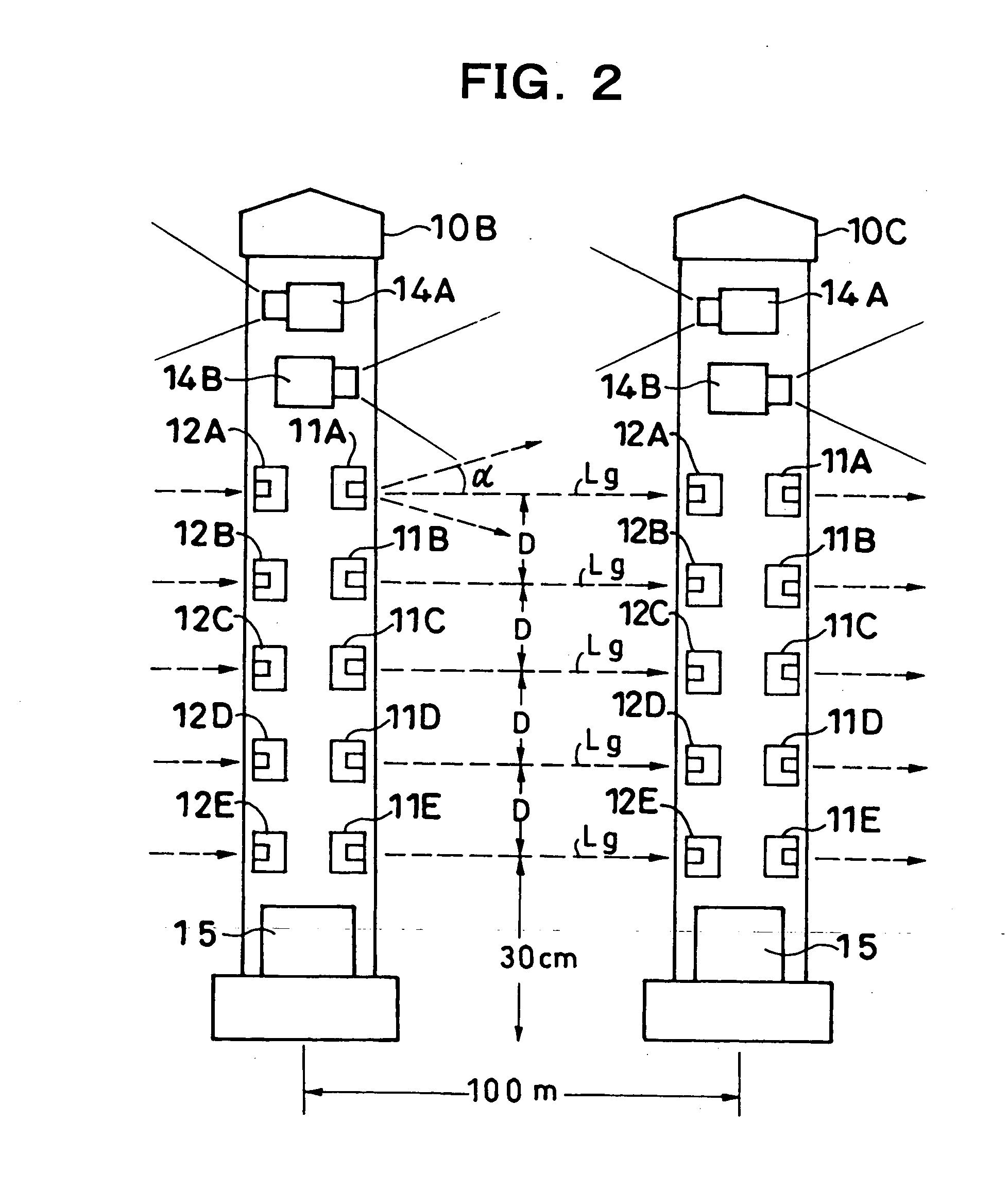
[0033] FIGS. 1 to 3 show the structure of the surveillance camera unit (or a complex surveillance camera unit) according to the embodiment, and in the example concerned, eight main bodies 10A to 10H are arranged and installed in a line at intervals of about 100 m (seven sections). As shown in FIG. 2, in each of the main bodies 10A to 10H (height 1.5 to 2 m), floodlighting units (floodlighting elements) 11A to 11E and photodetector units 12A to 12E (photodetector elements) are located in order at different height at each interval of D (30 cm to 50 cm) as, for example, five infrared sensors (five optical axes). The floodlighting unit 11E and photodetector unit 12E at lowest steps are located at the height of 30 cm from a ground surface. Thereby, it is possible to sufficiently detect an intruder (H2 in FIG. 10 (A)) who crawls and invades. In addition, in the main bodies 10A and 10E in end portions at the time of not being located annularly, it is sufficient to locate only one set of th...


PUM


Abstract

Five infrared sensors are located in different height positions between respective main bodies 10A to 10H, and all of these infrared sensors transmit and receive 35 infrared rays pulse-coded in conformity with a start-stop system. In addition, these pulse-coded infrared rays have the signal width of, for example, 450 μs, and are serially transmitted with a predetermined delay time in a period of 20 ms by a delayed synchronizing-signal. Intrusion surveillance is performed by identifying the pulse codes of these infrared rays. According to this, since not only interference among a plurality of infrared sensors is prevented, but also infrared rays are outputted in a short time, the occurrence of false alarms etc. decreases remarkably.

Description

BACKGROUND OF THE INVENTION [0001] 1. Field of the Invention [0002] The present invention relates to a surveillance system, and in particular, to structure for detecting an intruder and an intruding object in a surveillance system which embeds a camera and continuously monitors an intruder and an intruding object day and night into a controlled area such as an airport or a power plant. [0003] 2. Description of the Related Art [0004] Up to now, in controlled areas such as an airport, a power plant, and a special building and a facility, and ecology investigations of nature animals, the detection of an intruder and an intruding object, where an infrared sensor has been used, surveillance (observation) by camera photographing, analyses of images photographed with a camera, and the like have been performed. Then, the transmission and reception of an infrared ray is performed by a pulse count system, a modulation frequency switching-system, or the like in the above-mentioned infrared sen...

Claims


Application Information

Patent Timeline
IPC IPC(8): H04N7/18H04N9/47
CPCG08B13/183H04N7/188
Inventor SHIMIZU, HIDEOKOBAYASHI, YUKIOTAGUCHI, SATORU
Owner UNTERHALTUNGSSOFTWARE SELBSTKONTROLLE
Learn More