Thermometry probe calibration method

a technology of thermometer and calibration method, which is applied in the field of thermometer calibration method, can solve the problems of inability to wait the full amount of time for thermometer users, lack of accounting for variations in probe construction/manufacturing, and inability to use predictive thermometer apparatus techniques to normalize these types of effects, etc., and achieves significant cost and time savings, easy normalization, and minimized or normalized manufacturing specific differences of probes

Inactive Publication Date: 2006-04-06
WELCH ALLYN INC
View PDF52 Cites 15 Cited by
  • Summary
  • Abstract
  • Description
  • Claims
  • Application Information

AI Technical Summary

Benefits of technology

[0020] An advantage of the present invention is that the manufacturing effects of various temperature probes can be easily normalized for a thermometry apparatus.
[0021] Another advantage is that manufacturability or manufacturing specific differences of a probe can be minimized or normalized when in use, providing significant savings in cost and time.

Problems solved by technology

A problem with the above approach is that most users of thermometry systems cannot wait the full amount of time for thermal equilibrium, which is typically where the offset parameters are taken.
A fundamental problem with current thermometry systems is the lack of accounting for variations in probe construction / manufacturing that would affect the quality of the early rise time data.
To date, there has been no technique utilized in a predictive thermometer apparatus for normalizing these types of effects.

Method used


Image

  • Thermometry probe calibration method
  • Thermometry probe calibration method
  • Thermometry probe calibration method

Examples


Embodiment Construction

[0031] The following description relates to the calibration of a particular medical thermometry apparatus. It will be readily apparent that the inventive concepts described herein are applicable to other thermometry systems and therefore this discussion should not be regarded as so limiting.

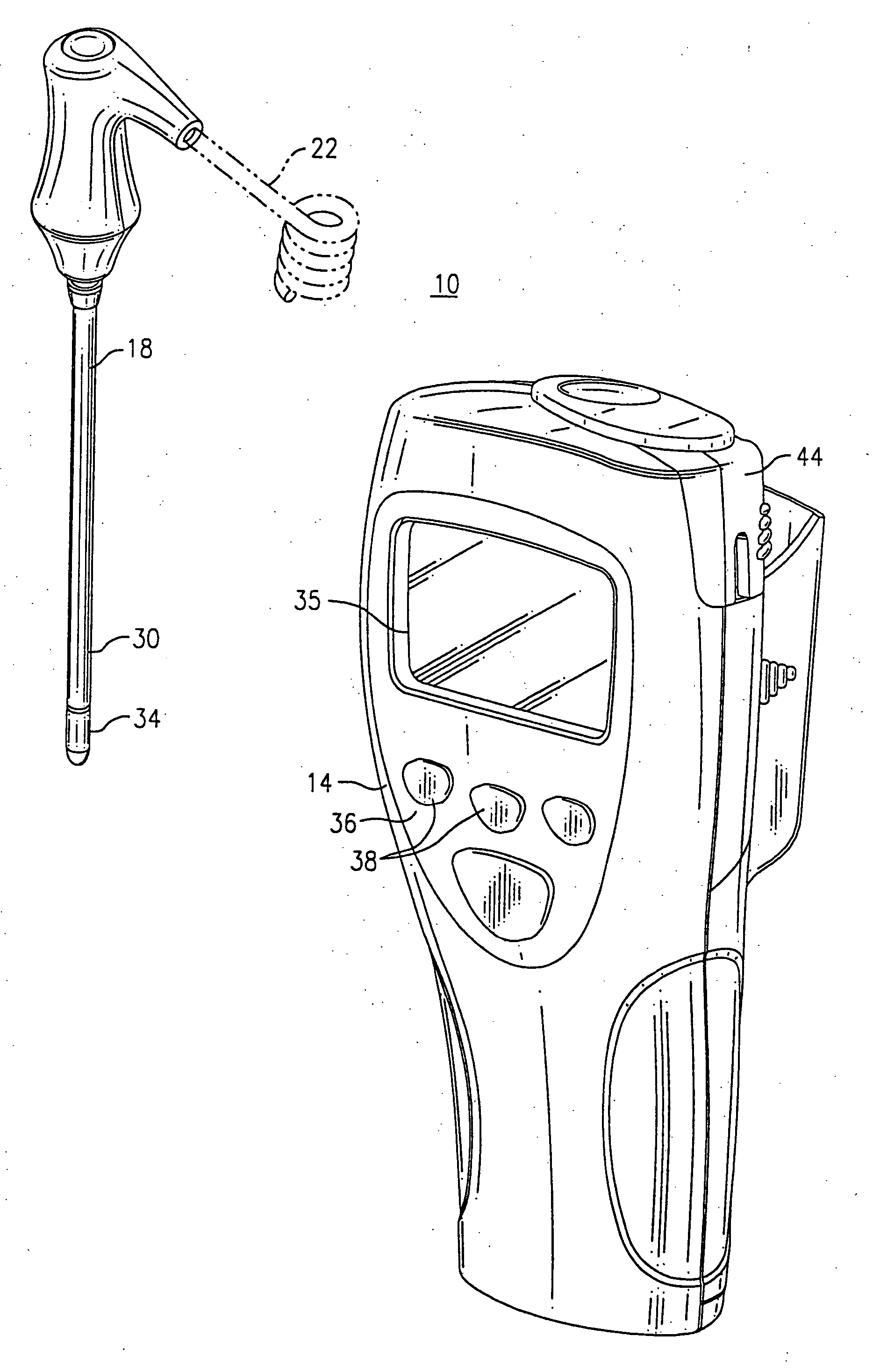
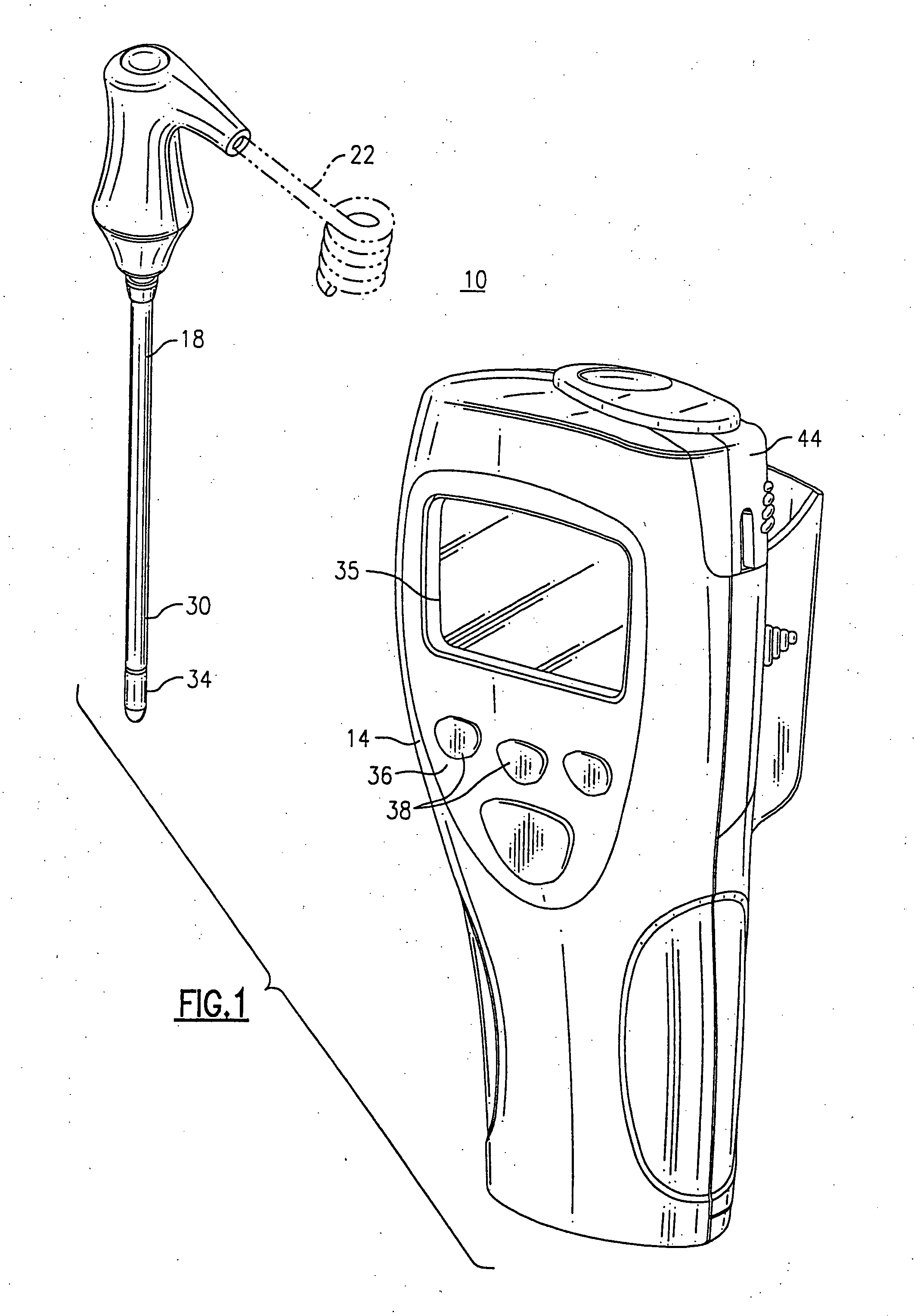
[0032] Referring first to FIG. 1, there is shown a temperature measuring apparatus 10 that includes a compact housing 14 and a temperature probe 18 that is tethered to the housing by means of a flexible electrical cord 22, shown only partially and in phantom in FIG. 1. The housing 14 includes a user interface 36 that includes a display 35, as well as a plurality of actuable buttons 38 for controlling the operation of the apparatus 10. The apparatus 10 is powered by means of batteries (not shown) that are contained within the housing 14. As noted, the temperature probe 18 is tethered to the housing 14 by means of the flexible cord 22 and is retained within a chamber 44 which is releasably attache...


PUM

PropertyMeasurementUnit
temperatureaaaaaaaaaa
timeaaaaaaaaaa

Abstract

A method in which thermal mass and manufacturing differences are compensated for in thermometry probes by storing characteristic data relating to individual probes into an EEPROM for each probe which is used by the temperature apparatus.

Description

CROSS REFERENCE TO RELATED APPLICATIONS [0001] This application is a divisional patent of U.S. patent application Ser. No. 10 / 683,206, filed Oct. 10, 2003, which is a continuation-in-part application of U.S. Ser. No. 10 / 269,461, now abandoned, filed Oct. 11, 2002, the entire contents of each being incorporated by reference.FIELD OF THE INVENTION [0002] This invention relates to the field of thermometry, and more particularly to a method of calibrating temperature measuring probes for use in a related apparatus. BACKGROUND OF THE INVENTION [0003] Temperature sensors in thermometric devices, such as patient thermometers, have typically been ground to a certain component calibration which will affect the ultimate accuracy of the device. These components are then typically assembled into precision thermometer probe assemblies. [0004] In past improvements, static temperature measurements or “offset type coefficients” have been stored into the thermometer's memory so that they can be eith...

Claims


Application Information

Patent Timeline
Patent Type & Authority Applications(United States)
IPC IPC(8): G01K7/00G01K7/42G01K15/00
CPCG01K7/42G01K15/005
Inventor QUINN, DAVID E.BURDICK, KENNETH J.STONE, RAY D.LANE, JOHNCUIPYLO, WILLIAM N.
Owner WELCH ALLYN INC
Why Eureka
Try Eureka