Loudspeaker apparatus

a technology of loudspeaker and amplifier, which is applied in the direction of transducer diaphragm, transducer details, electrical transducers, etc., can solve the problems of inconvenient lowering of acoustic signals, inability to obtain the necessary acoustic pressure on high frequencies of 20 khz or more, and inability to firmly fix diaphragm and the reinforcement ring

Inactive Publication Date: 2006-04-06
SONY CORP
View PDF3 Cites 24 Cited by
  • Summary
  • Abstract
  • Description
  • Claims
  • Application Information

AI Technical Summary

Benefits of technology

[0015] According to an embodiment of the present invention, as the adhered state in which a reinforcement ring adheres to a diaphragm, a favorable adhered state is obtained in which air is not left because of the permeability of the reinforcement ring itself, and so the reinforcement ring sticks firmly to the diaphragm, thereby surely reinforcing a bobbin attachment portion of the diaphragm. Therefore, the mechanical strength of a junctional flat portion of the diaphragm where a domed diaphragm and an edge-like diaphragm have been integrally molded can be enhanced, and thus the most efficient conversion from a vibration to an acoustic output can be performed, thereby providing a loudspeaker apparatus capable of reproducing up to a high frequency, for example 100 kHz.
[0017] Further, in that case, when using a thermoplastic adhesive as the adhesive applied to the reinforcement ring, the reinforcement ring can firmly be stuck to the diaphragm easily and surely without any space therebetween in the heat formation processing of the diaphragm.

Problems solved by technology

Particularly, if this dip is in the audible band, there has been an inconvenience in which the quality of acoustic signals is lowered.
Thus, a problem in which the necessary acoustic pressure may not be obtained on high frequencies of 20 kHz or more remains to be solved.
However, if a reinforcement ring is stuck and fixed when a loudspeaker diaphragm is formed by joining a domed diaphragm and an edge-like diaphragm to be molded, the following problems will arise.
If a reinforcement ring is made of, for example, the above-mentioned resinous film, it is relatively easy to shape the resinous film into a reinforcement ring, but air is left between a diaphragm and the reinforcement ring when the diaphragm is molded, so that there is a problem that the diaphragm and the reinforcement ring are not firmly stuck to each other.
If air is left between a diaphragm and a reinforcement ring in this manner, adhesive strength between the reinforcement ring and the diaphragm decreases to the extent, eventually causing a problem in which the above-mentioned insufficient mechanical strength of a diaphragm may not be solved.

Method used


Image

  • Loudspeaker apparatus
  • Loudspeaker apparatus
  • Loudspeaker apparatus

Examples


Embodiment Construction

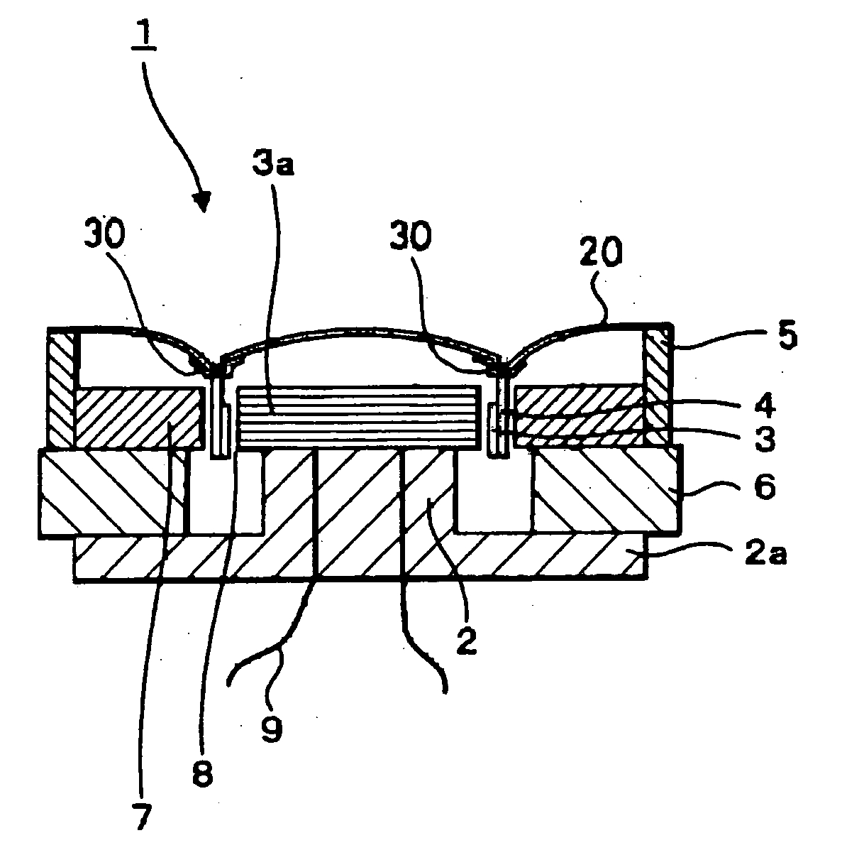
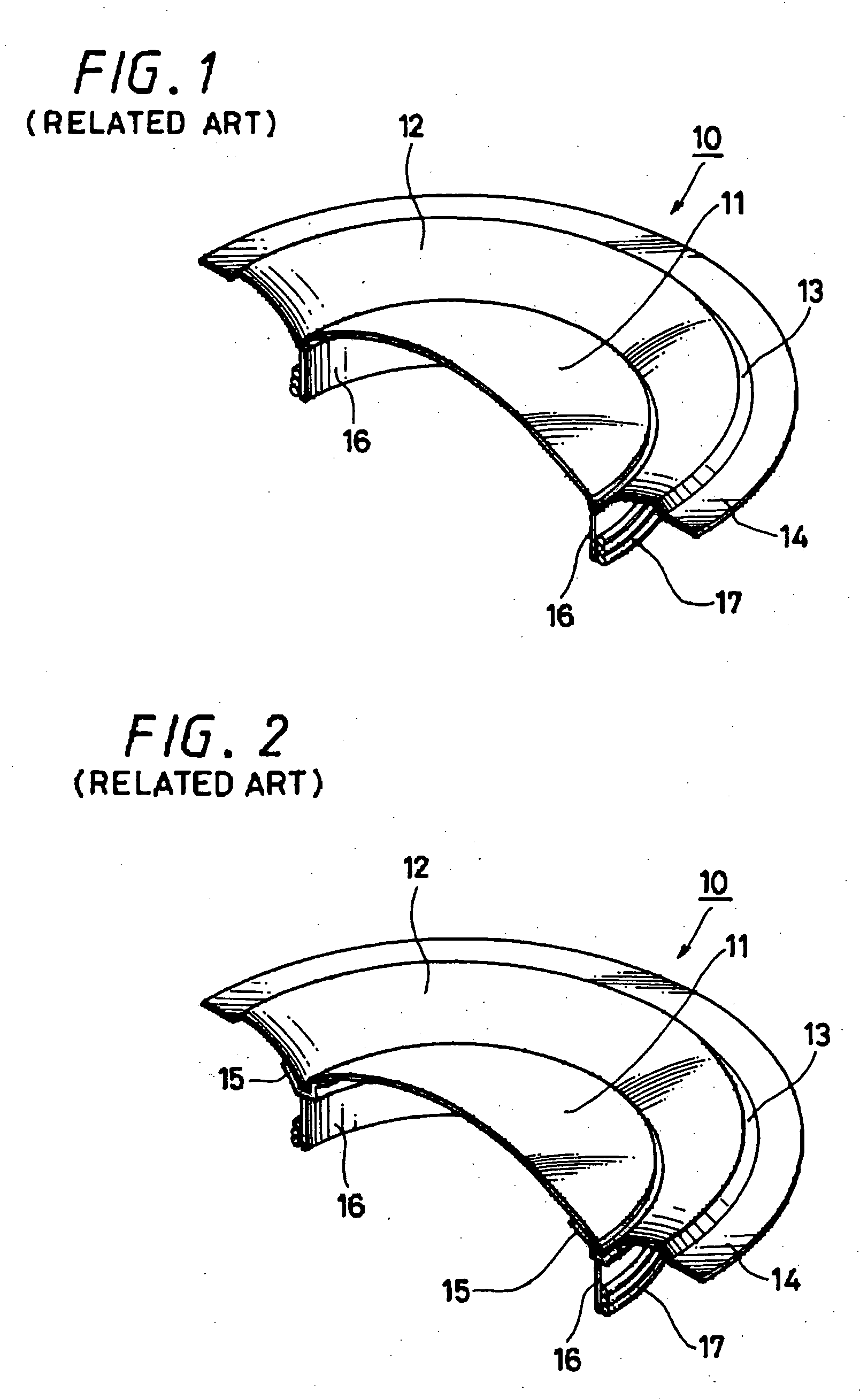
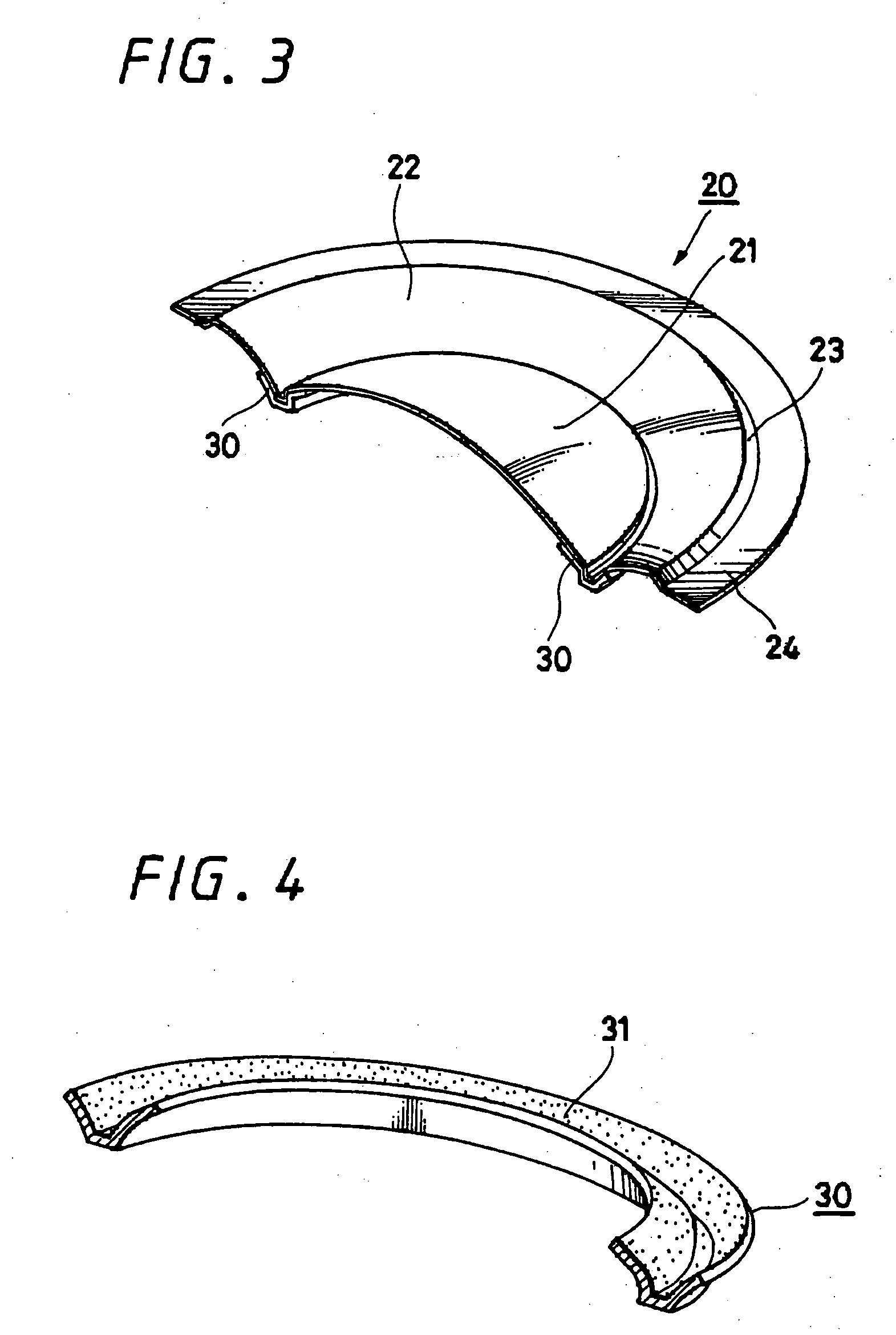
[0027] Hereinafter, an embodiment of the present invention will be explained referring to FIGS. 3 to 8.

[0028] This embodiment shows an example in which the present invention is applied to a dynamic electromagnetic induction loudspeaker, and first the whole construction of the dynamic electromagnetic induction loudspeaker of this embodiment is explained, referring to FIGS. 5 and 6. FIG. 5 shows a sectional side view of a dynamic electromagnetic induction loudspeaker of this embodiment, and FIG. 6 shows an equivalent circuit of the dynamic electromagnetic induction loudspeaker shown in FIG. 5.

[0029] In FIG. 5, a loudspeaker apparatus 1 includes a frame portion, an acoustic diaphragm and drive means. The frame is integrally formed with a lower surface plate 2a made of a disk-shaped metal in the approximate center of the lower surface plate 2a, a columnar pole piece 2 which is smaller in diameter than the lower plate is provided in an upright position, and a concentric magnet 6 is joi...


PUM


Abstract

A loudspeaker apparatus in which a diaphragm is reinforced easily and favorably. The loudspeaker apparatus includes a loudspeaker diaphragm formed by joining a domed diaphragm and an edge-like diaphragm and vibrated using a voice coil, and a reinforcement ring reinforcing a junctional flat portion or the vicinity of the junctional flat portion of the diaphragm. The reinforcement ring is formed of a permeable material, and the permeable reinforcement ring is stuck to the junctional flat portion or the vicinity of the junctional flat portion of the diaphragm.

Description

CROSS-REFERENCE TO RELATED APPLICATIONS [0001] The present application claims priority from Japanese Patent Application No. JP 2004-292875 filed on Oct. 5, 2004, the disclosure of which is hereby incorporated by reference herein. BACKGROUND OF THE INVENTION [0002] The present invention relates to a loudspeaker apparatus used for a variety of acoustic devices, video devices and the like, particularly to a loudspeaker apparatus in which the strength of a junctional flat portion of an acoustic diaphragm has been improved. [0003] As an acoustic diaphragm used for a loudspeaker apparatus in related art, there is an acoustic diaphragm 10 shown in FIG. 1, for example. FIG. 1 shows a construction which has been cut in half for an explanation. The acoustic diaphragm 10 includes a domed diaphragm 11 shaped like a dome in the center, and an edge-like diaphragm 12, which is formed of a macromolecular film, metal or the like, and is integrally formed in such a manner as to have a predetermined c...

Claims


Application Information

Patent Timeline
Patent Type & Authority Applications(United States)
IPC IPC(8): H04R11/02
CPCH04R7/127H04R7/18H04R9/045H04R9/06H04R31/003H04R31/006H04R9/02H04R9/04
Inventor OHASHI, YOSHIOURYU, MASARU
Owner SONY CORP
Why Eureka
Try Eureka