
Property independent in-place editing

Inactive Publication Date: 2006-04-06
MICROSOFT TECH LICENSING LLC
View PDF51 Cites 19 Cited by
  • Summary
  • Abstract
  • Description
  • Claims
  • Application Information

AI Technical Summary

Benefits of technology

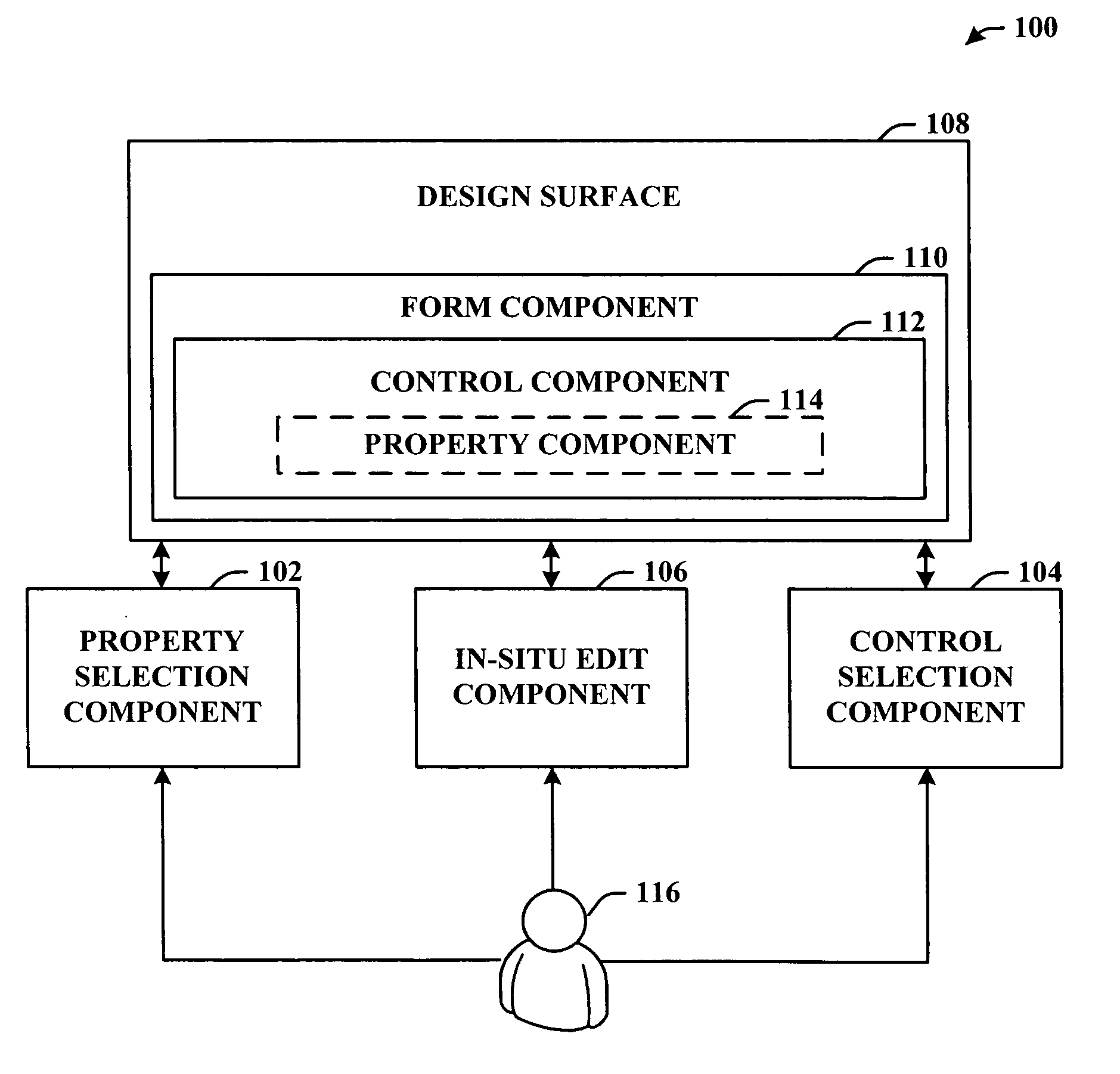
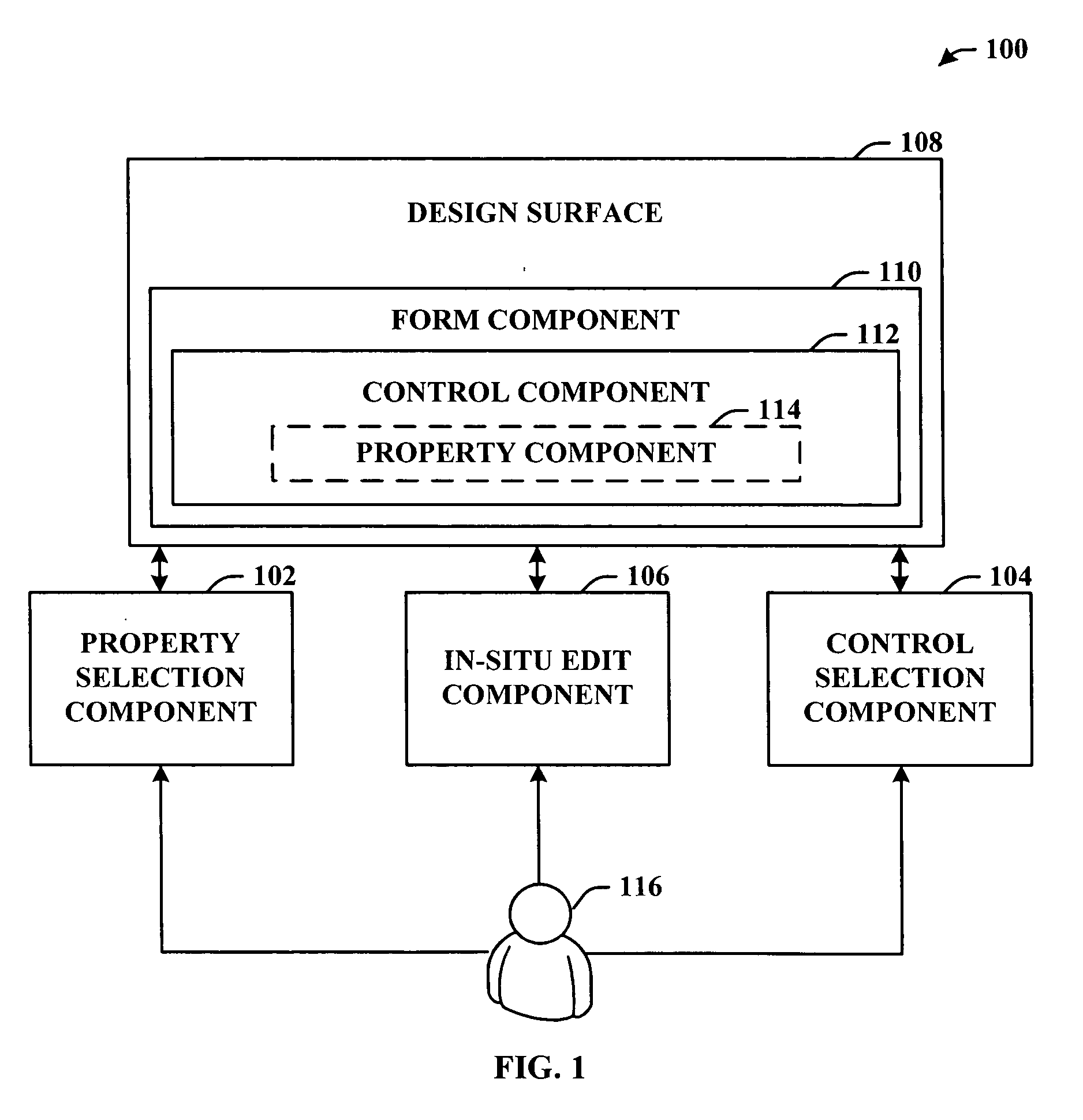
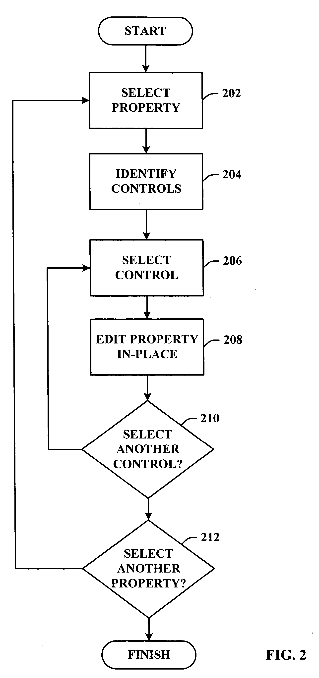
[0010] The subject invention disclosed and claimed herein, in one aspect thereof, provides for “in-situ editing” of a control property. “In-situ editing” refers to a feature that can allow a user (e.g., developer) to easily perform multi-pass configuration operations on their user interface (UI) components. This can be achieved by introducing the concept of a new editing mode or view to the integrated development environment (IDE)—(e.g., a Property Editing View (PEV)). The PEV mode can be active. In other words, the user can be presented with a mechanism of viewing and editing all properties without having to move off of the design surface. For example, editing can be performed on the design surface (e.g., in-place) thereby eliminating the conventional need to enter a property grid.
[0013] In an accordance with another aspect of the invention, a system that facilitates in-situ (e.g., in-place) editing of a property in a visual designer is provided. The system can include a property selection component that facilitates identifying the property. As described supra, the property selection component can employ a list component to display and thereby assist in effecting the identification and / or selection of the property. The list component can be arranged in any manner known in the art including but, not limited to, a drop-down, pull-down, alphabetical list or the like.

Problems solved by technology

This process is extremely time consuming, repetitive and, therefore, inefficient.
A moderately complex form may contain over one hundred controls—this can be a significant task.
These attempts, however, have been strictly limited to the Text property of the control.
This control dictated method leads to inconsistent user experience and implementation.
In other words, much of the user's attention should be concentrated on either the design surface or code editor, but unfortunately, for many tasks, the user must spend some time—or in some cases, a great deal of time—“outside” of these primary views to get their job done.
As well, no two developers are likely to progress through the phases in exactly the same order and manner.

Method used


Image

  • Property independent in-place editing
  • Property independent in-place editing
  • Property independent in-place editing

Examples


Embodiment Construction

[0031] The subject invention is now described with reference to the drawings, wherein like reference numerals are used to refer to like elements throughout. In the following description, for purposes of explanation, numerous specific details are set forth in order to provide a thorough understanding of the subject invention. It may be evident, however, that the subject invention can be practiced without these specific details. In other instances, well-known structures and devices are shown in block diagram form in order to facilitate describing the subject invention.

[0032] As used in this application, the terms “component” and “system” are intended to refer to a computer-related entity, either hardware, a combination of hardware and software, software, or software in execution. For example, a component can be, but is not limited to being, a process running on a processor, a processor, an object, an executable, a thread of execution, a program, and / or a computer. By way of illustrat...


PUM


Abstract

“In-situ editing” of a control property within a design surface is provided. “In-situ editing” refers to a feature that can allow a user (e.g., developer) to easily perform multi-pass configuration operations on their user interface (UI) components. This can be achieved by introducing the concept of a new editing mode or view to the integrated development environment (IDE)—(e.g., a Property Editing View (PEV)). The PEV mode can be active. In other words, the user will be presented with a mechanism of viewing and editing all properties without having to move off of the design surface. For example, editing can be performed in-place eliminating the conventional need to enter a property grid.

Description

TECHNICAL FIELD [0001] This invention is related to computer systems and more particularly to a system and / or methodology to effect in-situ (e.g., in-place) editing of a control property within a visual forms designer. BACKGROUND OF THE INVENTION [0002] Visual user interface (UI) designers (e.g., Visual Basic or Visual Studio.NET brand designers) regularly employ properties in the design process. Design elements generally have properties such as Name, Text, Size, Color, etc. Some of these properties, such as Size or Location can be easily set with the mouse and do not require keyboard input. Other properties (e.g., Name, Text), however, are updated through a Property Browser interface which requires tedious cycles such as “select component”, “select property”, “set value,” etc. This process is extremely time consuming, repetitive and, therefore, inefficient. For example, on a form with UI elements (often referred to as “controls”), users almost always have to change the “Text” and “...

Claims


Application Information

Patent Timeline
IPC IPC(8): G06F17/00
CPCG06F9/4443G06F9/451
Inventor BURKE, SHAWN P.CHRISOPE, JEFFREY T.
Owner MICROSOFT TECH LICENSING LLC
Learn More