Moisture diverting insulated siding panel

a technology of insulating siding panels and moisture-distributing layers, which is applied in the direction of water-setting substances layered products, transportation and packaging, and other domestic articles, can solve the problems of limiting the ability of siding veneers to successfully weep away moisture, significant damage to wall systems and building structures, and affecting the performance of insulation and acoustic insulation, so as to reduce scrap waste, improve handling and assembly, and reduce thermal and acoustic insulation performance

Inactive Publication Date: 2006-04-13
CERTAINTEED CORP
View PDF99 Cites 98 Cited by
  • Summary
  • Abstract
  • Description
  • Claims
  • Application Information

AI Technical Summary

Benefits of technology

[0007] Use of an insulation backing that comprises more than one insulation member helps to reduce scrap waste and improve handling and ease of assembly, all without reducing thermal and acoustic insulation performance.
[0008] In another embodiment of a siding panel product, the siding panel product includes one or more insulation members coupled to the rear surface of the siding panel where the one or more insulation members includes a plurality of spacing elements on at least one of the major surfaces thereof forming at least one channel. Depending on the orientation of the spacing elements, the insulated siding product can provide for a better adhesive connection between the insulation backing and the siding panel, and / or provide for improved or enhanced water drainage. Improved drainage can provide a diminished probability of occurrence of mold, mildew and / or rot formation behind a siding panel product. In some embodiments, the siding product includes an improved locking means that provides for an easier installation of the siding product, thereby providing both cost and manpower savings.

Problems solved by technology

The advent of the insulation layer attached to the back of the siding creates a barrier which significantly limits the ability of the siding veneer to successfully weep this moisture away.
Moisture can become trapped between the insulation layer and the siding panel and between the building wall and the insulation layer.
The trapped moisture can cause significant damage to wall systems and building structures as well as significantly reduce the effectiveness of the insulation materials as they become saturated.

Method used


Image

  • Moisture diverting insulated siding panel
  • Moisture diverting insulated siding panel
  • Moisture diverting insulated siding panel

Examples


Embodiment Construction

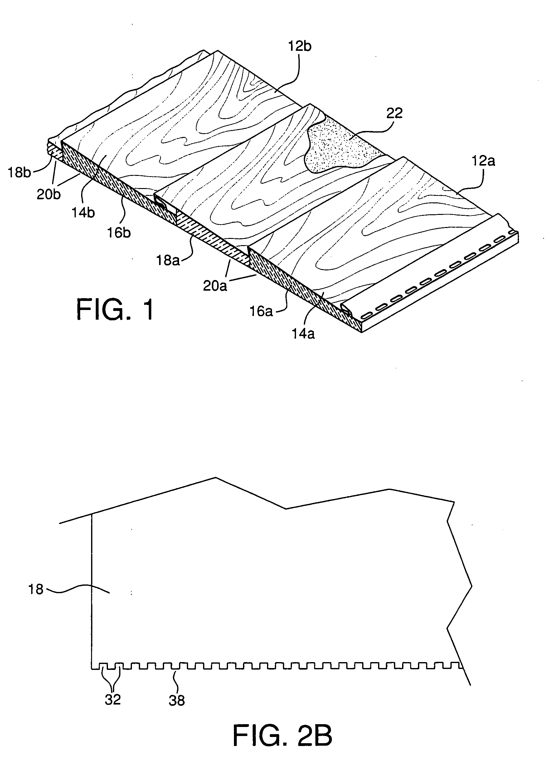
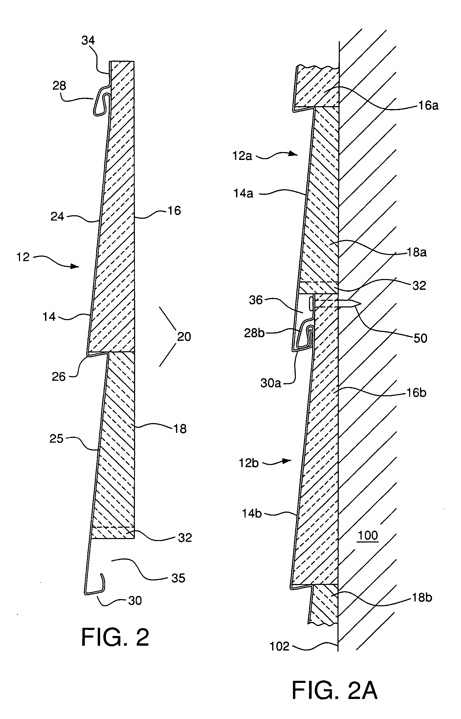
[0022] Provided herein is an improved insulation product comprising a thin walled polymeric siding panel and an insulation backing coupled thereto. FIG. 1 is a partial perspective view showing two coupled insulation products 12a, 12b according to a first embodiment. As can be seen from FIG. 1 and as described in more detail in connection with FIGS. 2 and 2A, each insulation product 12a, 12b includes a respective siding panel 14a, 14b coupled, in a preferred embodiment, by an adhesive 22 to respective insulation backing 20a, 20b. The panels can be coupled to insulation members, such as layers, panels, boards or coatings (hereinafter collectively referred to as “members”), for example. In the embodiment shown in FIG. 1, each insulation backing 20a, 20b comprises a plurality of insulation members 16a, 18a and 16b, 18b, respectively, which are described in more detail below in connection with FIGS. 2 and 2A.

[0023]FIG. 2 is a profile view of an individual siding panel product 12 shown i...


PUM

PropertyMeasurementUnit
angleaaaaaaaaaa
depthaaaaaaaaaa
depthaaaaaaaaaa

Abstract

A siding panel product is provided comprising a first polymeric siding panel having a butt end and a top end, a front surface comprising a plurality of front faces defined between the top and butt ends and separated by at least one shoulder surface to define a stepped contour, and a rear surface. An insulation backing is coupled to the rear surface of the siding panel. The insulation backing comprises at least first and second insulation members coupled to the rear surface of said siding panel. The first insulation member has a bottom edge thereof coupled proximate to the stepped contour and the second insulation member has a top edge thereof coupled proximate to the stepped contour.

Description

CROSS-REFERENCE TO RELATED APPLICATION [0001] This application is a continuation-in-part of copending, commonly assigned U.S. patent application Ser. No. 10 / 955,405 to Rick James Morse, Robert D. Shaw and Gregory F. Jacobs, entitled “Foam Backed Fiber Cement” filed Sep. 30, 2004, the entirety of which is hereby incorporated by reference herein.FIELD OF THE INVENTION [0002] The present invention relates to building materials generally, and more specifically to siding panel building materials. BACKGROUND [0003] Current insulated siding panels are designed to create a thermal barrier layer behind a thin vinyl siding layer. The lower butt sections of these vinyl siding layers are generally designed with weep holes to allow moisture trapped behind the siding to escape or weep out. This moisture can come from wind blown rain, condensation or other source. An example of one prior art insulated siding panel system is provided in U.S. Pat. No. 6,029,415 to Culpepper et al. (the “'415 Patent”...

Claims


Application Information

Patent Timeline
Patent Type & Authority Applications(United States)
IPC IPC(8): E04D1/00
CPCB32B5/18B32B7/08B32B13/02B32B13/045B32B13/12B32B2250/02B32B2262/04B32B2266/025B32B2266/0278B32B2266/08B32B2307/712B32B2307/7265B32B2419/04B32B2419/06B32B2607/00E04F13/0864E04F13/141Y10T428/249953Y10T428/249976Y10T428/249982E04F13/077E04F13/185E04F13/0869E04F13/0871E04F13/0866
Inventor GILBERT, THOMAS C.JACOBS, GREGORY F.BECK, DAVID H.
Owner CERTAINTEED CORP
Why Eureka
Try Eureka