
Nondestructive verification of minimum tensile elongation of manufactured parts

a technology of manufacturing parts and tensile elongation, which is applied in the direction of measurement devices, instruments, scientific instruments, etc., can solve the problems of significant cost associated with machining and testing specimens, insufficient representation of bulk material properties, and material consumption, etc., and achieve the effect of easy sampling different parts in different areas

Inactive Publication Date: 2006-04-13
THE BOEING CO
View PDF5 Cites 8 Cited by
  • Summary
  • Abstract
  • Description
  • Claims
  • Application Information

AI Technical Summary

Benefits of technology

[0004] In accordance with an embodiment of the present invention, simple yet reliable, low-cost apparatus and methods are provided for the nondestructive, in-situ verification of the minimum tensile elongation specification of a manufactured part that eliminate the need for tensile coupons, and any question whether such coupons accurately represent the actual bulk properties of the manufactured part. Since the non-destructive elongation measurements are made within the parts themselves, material pedigree is no longer an issue. Advantageously, the novel method also applies stresses to a greater amount of the material of the part, and can easily sample different areas of the part, thereby enabling a closer, more thorough evaluation of the part's material bulk properties.

Problems solved by technology

In addition to the cost of the materials consumed in these tests, there are also significant costs associated with the machining and testing of the specimens.
Furthermore, the specimens may not adequately represent the true bulk material properties of the parts being evaluated, which can lead to erroneous test results.
A long-felt but as yet unsatisfied need therefore exists in the manufacturing industry for reliable, low-cost, apparatus and methods for the nondestructive verification of the minimum tensile elongation specification of a manufactured part that can be effected on the part itself, thereby eliminating the need for expensive tensile test coupons and equipment, and any question whether such coupons accurately represent the true bulk material properties of the manufactured part.

Method used


Image

  • Nondestructive verification of minimum tensile elongation of manufactured parts
  • Nondestructive verification of minimum tensile elongation of manufactured parts
  • Nondestructive verification of minimum tensile elongation of manufactured parts

Examples


Embodiment Construction

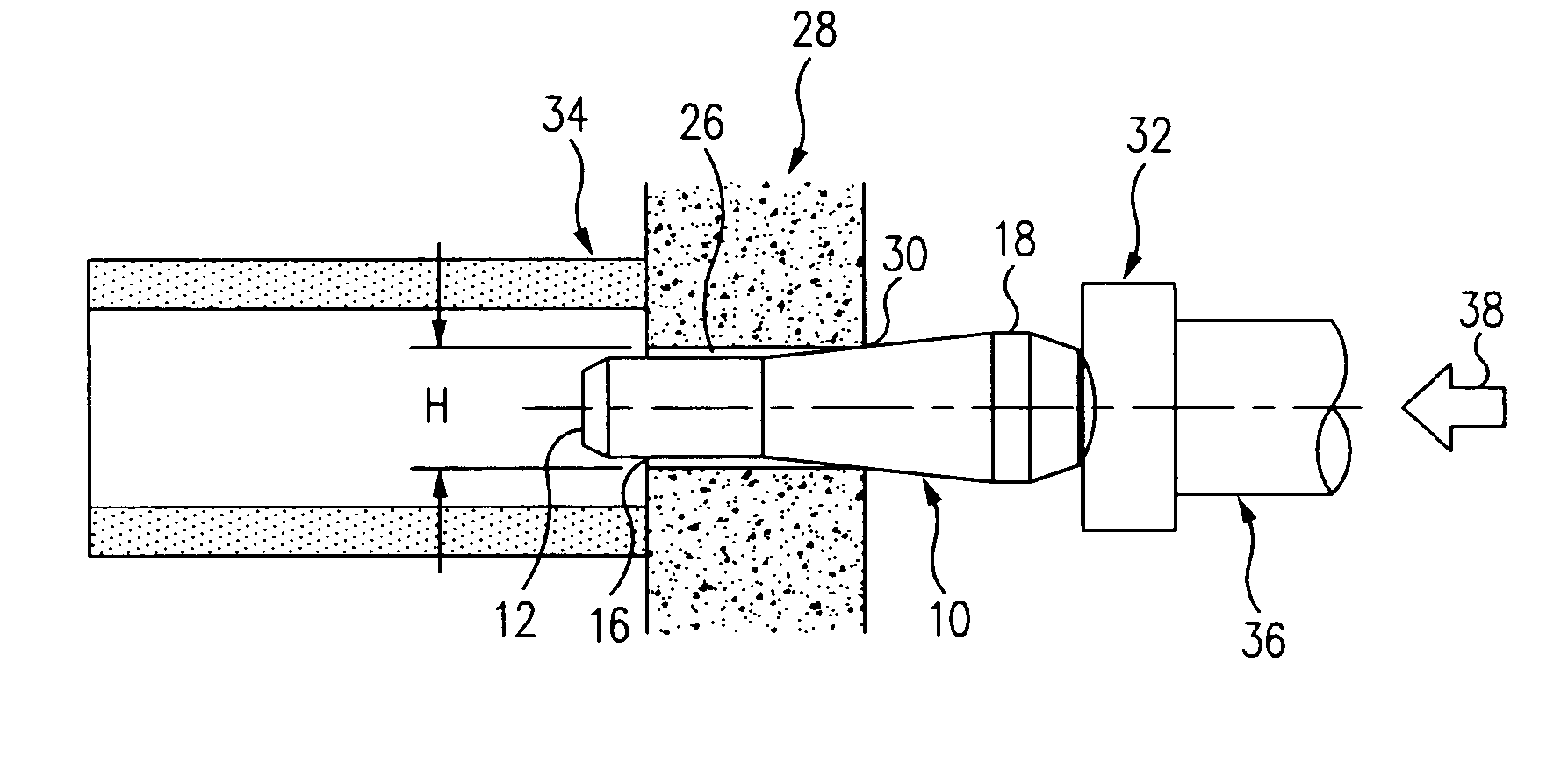
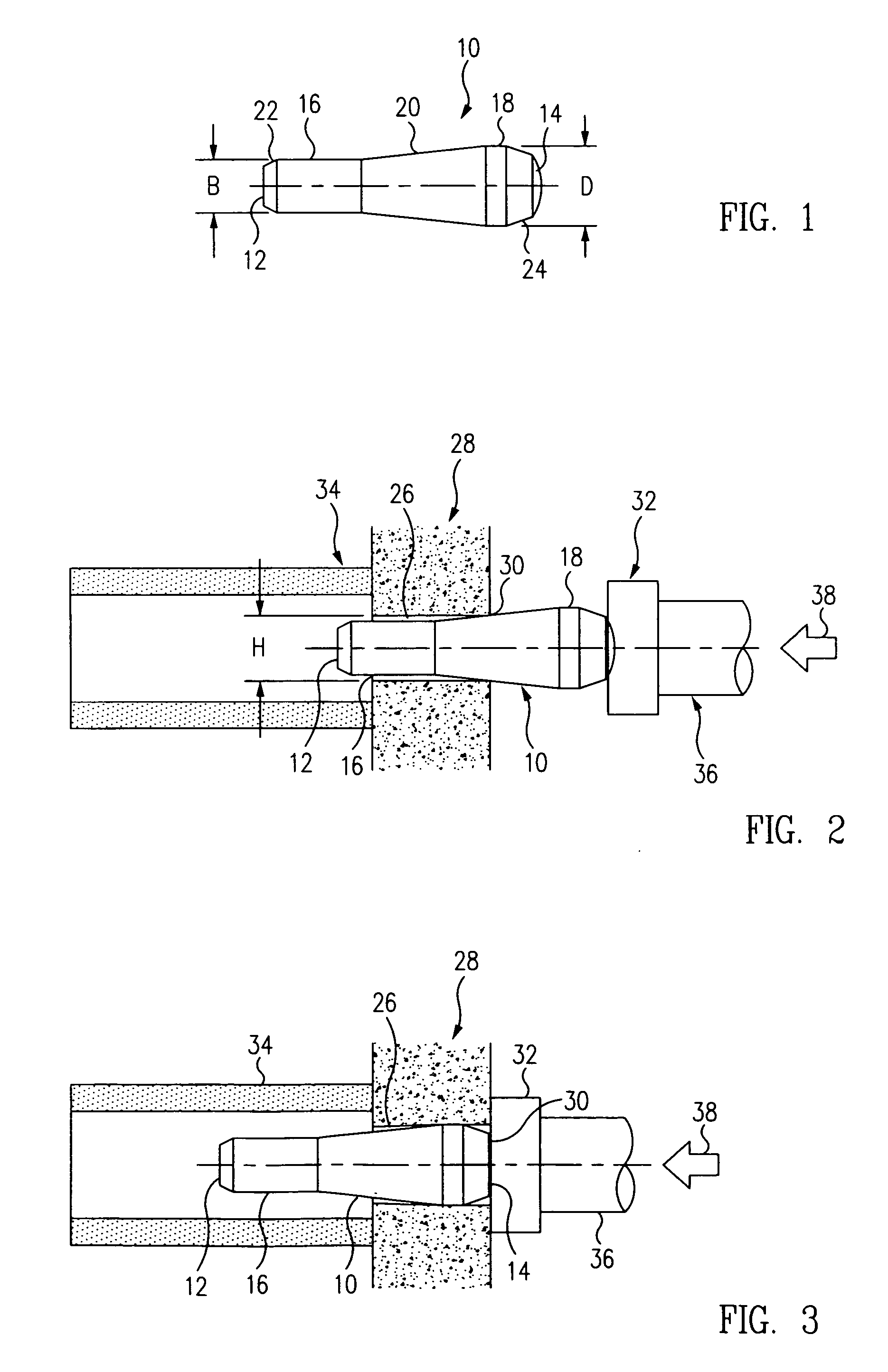
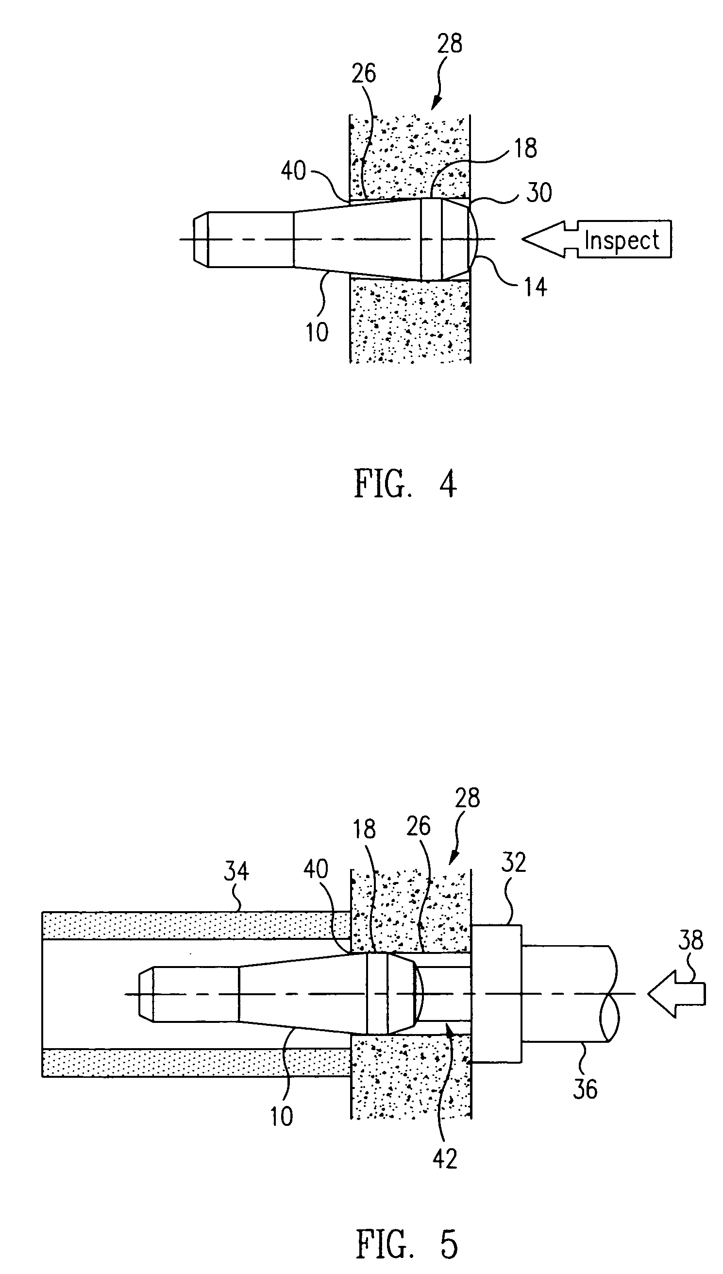
[0015] In accordance with an exemplary embodiment of the present invention, an inexpensive, disposable mandrel 10 and a few simple bench tool accessories are used in conjunction with a method to radially expand a test hole formed in a casting, forging, or other manufactured part by a prescribed amount to effect a circumferential strain at the edge of the hole matching minimum required elongation, or target strain, of the part. After the test hole has been radially expanded, the area in the vicinity of the test hole is inspected for radial cracks, which indicate that the part does not meet the elongation minima requirements. The apparatus and method can be used either to complement or completely replace existing standard tensile tests.

[0016] As illustrated in FIG. 1, the apparatus of the invention comprises an elongated, tapered mandrel 10 that is used to radially expand a pre-lubricated test hole that has been formed in the part to be tested. The mandrel has opposite, respective fi...


PUM


Abstract

The minimum tensile elongation specification of a manufactured part, such as metal castings, forgings and premium mill products, is verified in-situ using a simple, inexpensive, nondestructive apparatus and method in which a through-hole is formed in the part to be tested. A disposable mandrel having a diameter adapted to expand the hole to the minimum elongation required in the part's specification is pressed into the hole. The presence of radial cracks in the part adjacent to the hole after the mandrel has been pressed in indicates that the part does not meet the specification, and the absence of such cracks indicates that it does. Since the test is performed on the part itself, the cost of the manufacture and testing of tensile test coupons is eliminated, and different areas of the part may be sampled easily, thereby enabling a closer, more thorough evaluation of part's material bulk properties.

Description

TECHNICAL FIELD [0001] This invention relates to the nondestructive testing of manufactured parts in general, and in particular, to apparatus and methods for the nondestructive, in-situ verification of the minimum tensile elongation specification of metal castings, forgings, and premium mill products such as plate, bar and extrusion, and molded parts and the like. BACKGROUND [0002] Specifications for metal castings, forgings and premium mill products such as plate, bar and extrusion, frequently include tensile elongation minima among their lot acceptance requirements. Elongations are measured using tensile test specimens, e.g., “coupons,” made from specially cast bars (“prolongs”), or material that is excised from the manufactured parts themselves, which are stretched in specialized tensile testing machines. In addition to the cost of the materials consumed in these tests, there are also significant costs associated with the machining and testing of the specimens. Furthermore, the s...

Claims


Application Information

Patent Timeline
IPC IPC(8): G01N3/08
CPCG01N3/08G01N2203/0017
Inventor RUFIN, ANTONIO C.
Owner THE BOEING CO
Learn More