Control device and method of manufacturing thereof

a control device and control device technology, applied in the direction of electrical apparatus construction details, electrical apparatus casings/cabinets/drawers etc., can solve the problems of insufficient consideration of the method of mounting module products in automobiles, farming machines, industrial machines or ships, and the inability to conduct an electrically stable ground smoothly, so as to improve the efficiency and reliability of the system, improve the emc resistance, and reduce the size

Active Publication Date: 2006-04-13
HITACHI ASTEMO LTD
View PDF2 Cites 43 Cited by
  • Summary
  • Abstract
  • Description
  • Claims
  • Application Information

AI Technical Summary

Benefits of technology

[0012] According to such a configuration, it is possible to obtain an electrical contact via a metallic base which is used also for mounting the module while maintaining such effects as improved productivity and reliability and reduced size resulting from encapsulating with a resin molding compound. Consequently, an electrically stable ground necessary for the improvement of EMC resistance can be conducted smoothly to the circuit board. Moreover, since the metallic base high in thermal conductivity can be disposed near heat-generating components, it is possible to improve the heat dissipating property. Further, since the metallic base is used for mounting the module, it is possible to effect mounting by the same method as the conventional module mounting method using a metallic base.
[0013] Such plural objects as improving EMC resistance, heat dissipating property and mounting property of a resin-sealed module can be achieved at a time without impairing productivity and reliability, by the addition of only a metallic base.

Problems solved by technology

However, the above conventional methods involve encapsulating with a resin molding for ensuring vibration resistance and complete air- and water-tightness, with no consideration given to EMC resistance as an important factor in operation reliability of an electronic circuit and to dissipation of heat generated from electronic components.
In addition, consideration has not been given sufficiently to the method of mounting module products in an automobile, a farming machine, an industrial machine or a ship.
Besides, the resins used in the above methods are electrical insulators and have heretofore been unable to conduct an electrically stable ground smoothly to a circuit board for the improvement of EMC resistance.
Therefore, the resins make it impossible to mount high heat generating electronic components within a circuit.
Therefore, mounting position and mounting method for satisfying required vibration resistance and resistance to deformation stress encounter limits with consequent deterioration of productivity.

Method used


Image

  • Control device and method of manufacturing thereof
  • Control device and method of manufacturing thereof
  • Control device and method of manufacturing thereof

Examples


first embodiment

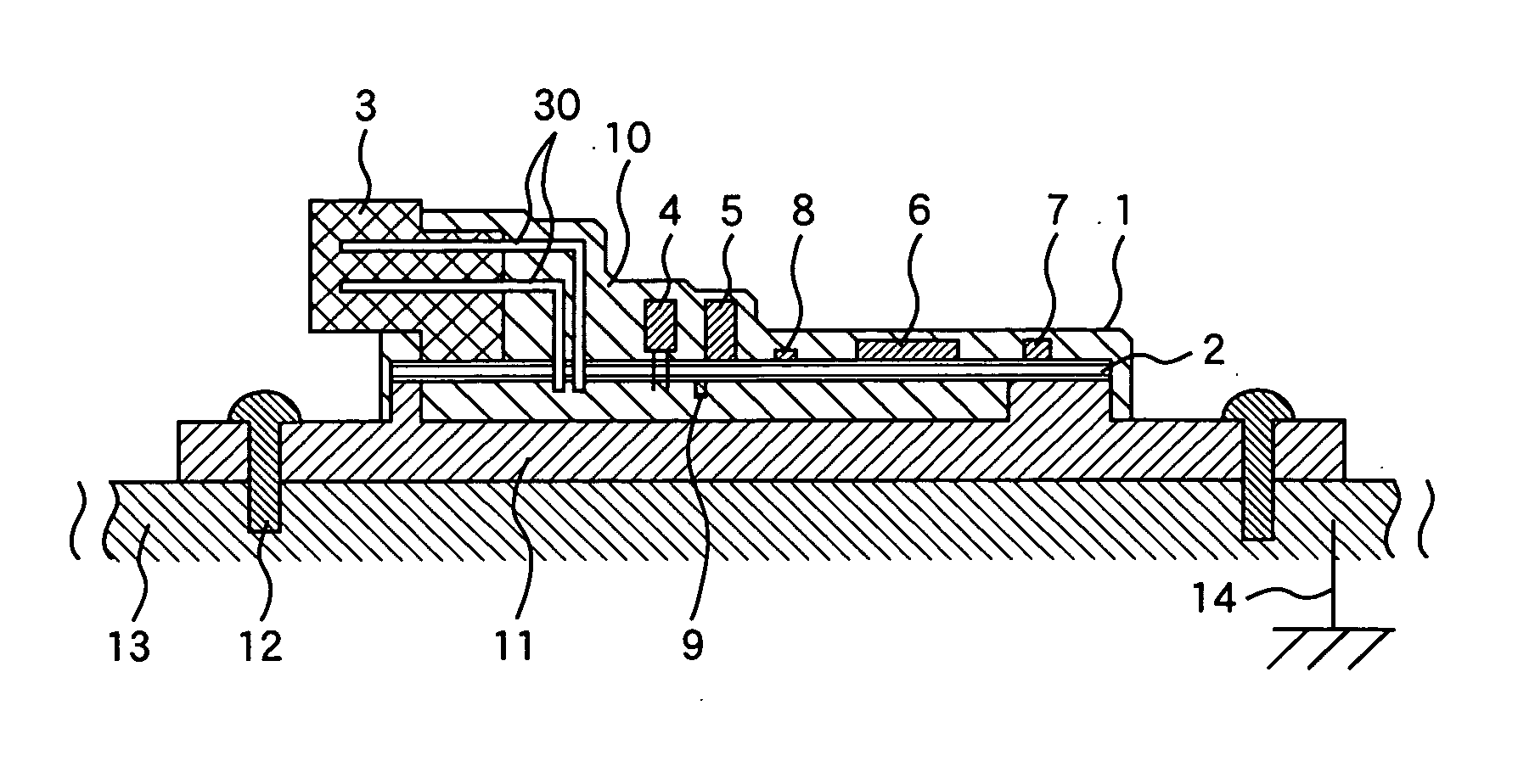
[0021]FIG. 1 is a sectional view showing the structure of a module 1 according to a first embodiment of the present invention.

[0022] In this module, a circuit board is populated with a connector 3 including a metallic terminal pins (connector pins) 30 and electronic components such as a circuit board insertion type electronic component 4, a surface-mounted type large-sized electronic component 5, an IC 6, a high heat generating electronic component 7, a surface-mounted chip type electronic component 8, and a back-mounted chip type electronic component 9 etc. A part of the connector 3, a part of the connector pins 30, the electronic components and the circuit board 2 for populating them are encapsulated with a resin molding compound 10.

[0023] A metallic base 11 (a metallic member) on which the circuit board is mounted is united with the circuit board 2 to provide an electric conduction between the metallic base 11 and the circuit board 2. The module 1 is for use, for example, in an...

second embodiment

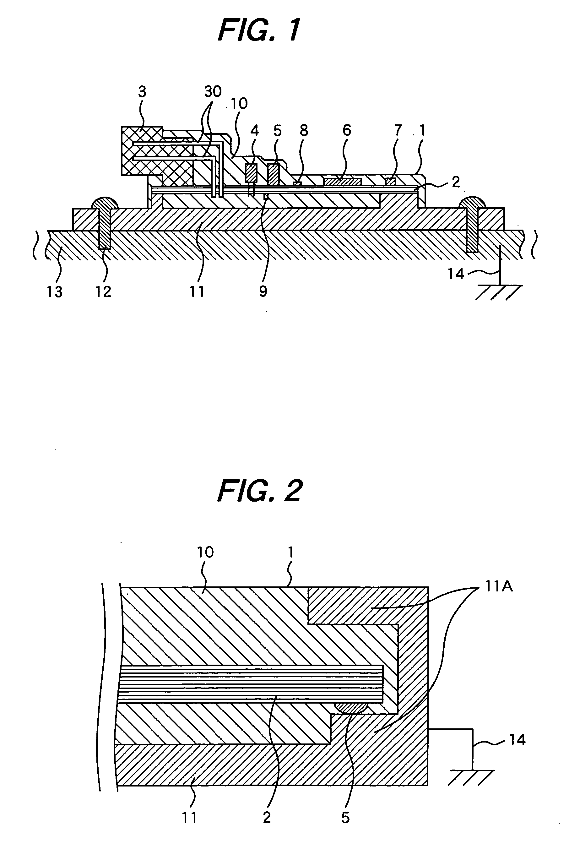
[0037]FIG. 2 is a partial sectional view showing the structure of a module 1 according to a second embodiment of the present invention which module is to be used, for example, in an automobile, a farming machine, an industrial machine or a ship. In this second embodiment, a difference from the previous first embodiment will be described as follows. The periphery 11A of the metallic base 11 has a form of a lateral U-shaped channel whose opening faces in an inward direction of the base 11. The periphery of the circuit board 2 which is in contact with the metallic base 11 is inserted into the lateral U-shaped channel of the metallic base 11, and resin for the resin molding compound 10 is poured and molded in the metallic base 11 at a high temperature and then cooled to the normal working temperature. The thermal expansion coefficient of the metallic base 11 is higher than that of the resin molding compound 10. As a result, according to the structure of the second embodiment, a thermal ...

third embodiment

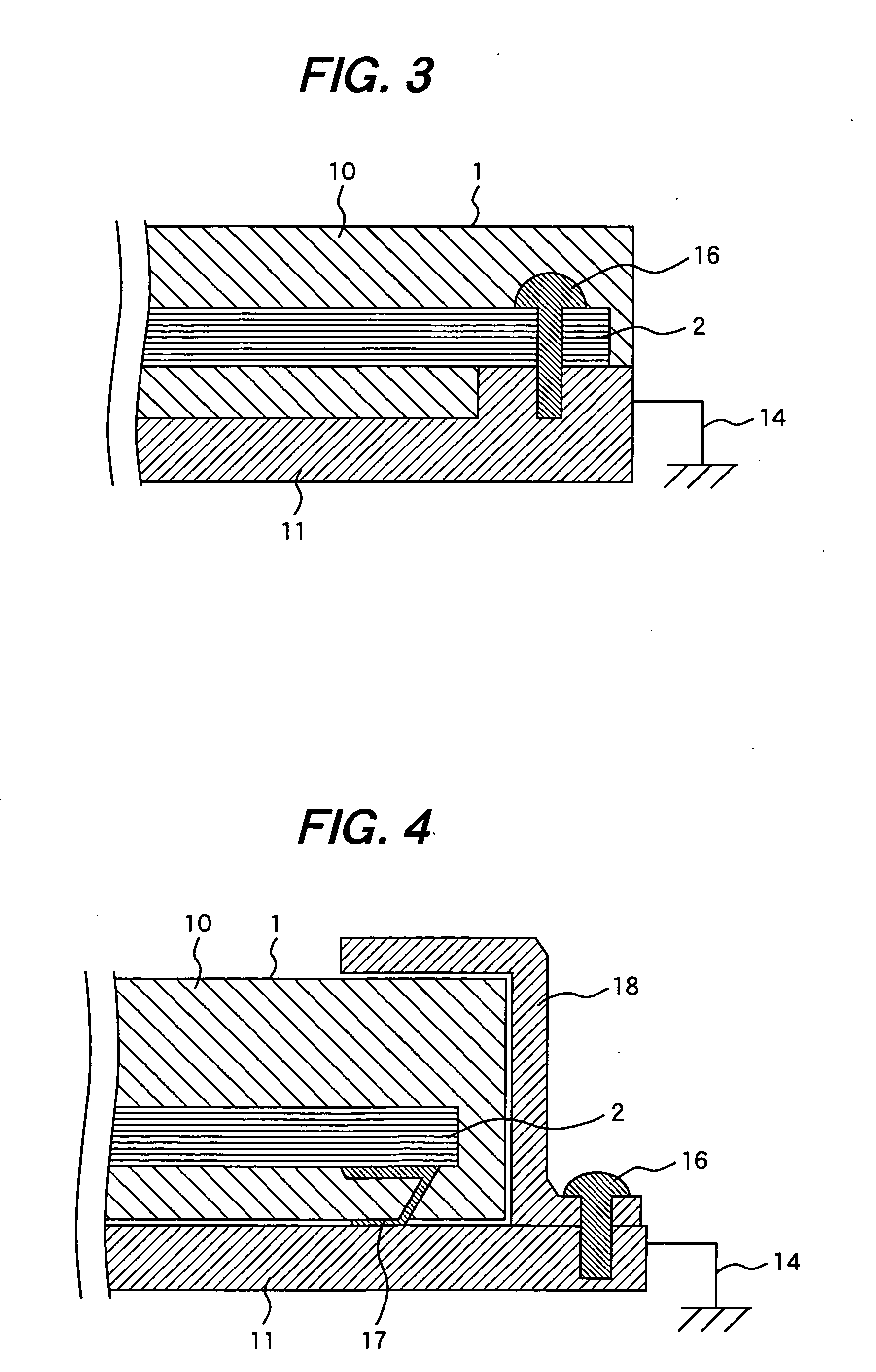
[0043]FIG. 3 is a partial sectional view showing the structure of a module 1 according to a third embodiment of the present invention which module is to be used, for example, in an automobile, a farming machine, an industrial machine or a ship. In this third embodiment, a difference from the first embodiment will be described as follows. The metallic base 11 and the circuit board 2 are kept in contact with each other using metallic base-fixing-screws 16 as in the conventional module not molded with resin. A stress acting to press the circuit board 2 against the metallic base 11 is produced by the screws 16. Thereby an electric connection between the metallic base 11 connected to the reference ground 14 and the circuit board 2 is attained more effectively than in the first embodiment.

[0044] The same mounting position of the metallic base 11 as in the first embodiment can be selected, but since the metallic base-fixing-screws 16 are passed through the circuit board 2, if the number o...


PUM

PropertyMeasurementUnit
heat resistanceaaaaaaaaaa
metallicaaaaaaaaaa
conductiveaaaaaaaaaa

Abstract

A module comprises a metallic terminal pins for connection and a circuit board with electronic components mounted thereon, a circuit board connecting side of the connector. The electronic components and the circuit board with the electronic components mounted thereon are encapsulated with the same resin. A metallic base is united to the module to obtain an electric conduction between the metallic base and the circuit board.

Description

CLAIM OF PRIORITTY [0001] The present application claims priority from Japanese application serial no. 2004-293183, filed on Oct. 6, 2004, the content of which are hereby incorporated by reference into this application. FIELD OF THE INVENTION [0002] The present invention relates to a control device having electronic components mounted on a circuit board, and encapsulating the electronic components and the circuit board with a resin molding compound. Particularly, the present invention relates to a control device suitable for use as any of various control modules and sensor modules mounted on, for example, automobiles, farming machines, industrial machines and ships, as well as a method of manufacturing the control device. BACKGROUND OF THE INVENTION [0003] Conventional various control modules (e.g., engine control module, motor control module, automatic transmission control module) mounted on automobiles, farming machines, industrial machines and ships have been disposed within a ve...

Claims


Application Information

Patent Timeline
Patent Type & Authority Applications(United States)
IPC IPC(8): H05K7/04
CPCB29C45/14639H05K1/0215H05K3/0061H05K3/284Y10T29/49146H05K3/3447H05K2201/09054H05K2201/10189H05K2201/2036H05K3/321H05K5/0034H05K5/0082H05K7/20854
Inventor MAYUZUMI, TAKUYAEGUCHI, SHUJISASAKI, MASAHIROKADOYA, KIYOOMI
Owner HITACHI ASTEMO LTD
Why Eureka
Try Eureka