Digital pre-distortion technique using nonlinear filters

a nonlinear filter and digital technology, applied in the field of digital pre-distortion technique using nonlinear filters, can solve the problems of ineffective memory effects, power amplifiers that not only exhibit nonlinear distortion, but also possess memory effects, and achieve moderate linearization improvement, the effect of reducing the cost of memory effects

Active Publication Date: 2006-04-13
MICROELECTRONICS TECH INC
View PDF12 Cites 52 Cited by
  • Summary
  • Abstract
  • Description
  • Claims
  • Application Information

AI Technical Summary

Problems solved by technology

Power amplifiers not only typically exhibit non-linear distortion but also possess memory effects.
However these techniques do not effectively handle memory effects and thus provide very moderate linearization improvements.
More importantly, power amplifiers are generally expensive and consume much power.
Multiple carrier applications, such as cellular telephone base stations, are particularly problematic inasmuch as a single amplifier is typical

Method used


Image

  • Digital pre-distortion technique using nonlinear filters
  • Digital pre-distortion technique using nonlinear filters
  • Digital pre-distortion technique using nonlinear filters

Examples


Embodiment Construction

[0018] Illustrative embodiments and exemplary applications will now be described with reference to the accompanying drawings to disclose the advantageous teachings of the present invention.

[0019] While the present invention is described herein with reference to illustrative embodiments for particular applications, it should be understood that the invention is not limited thereto. Those having ordinary skill in the art and access to the teachings provided herein will recognize additional modifications, applications, and embodiments within the scope thereof and additional fields in which the present invention would be of significant utility.

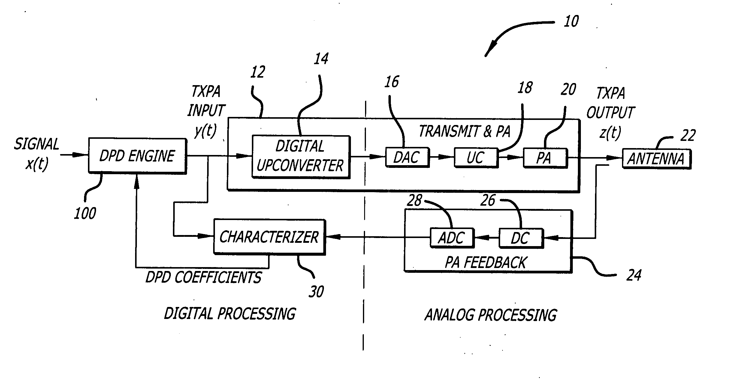
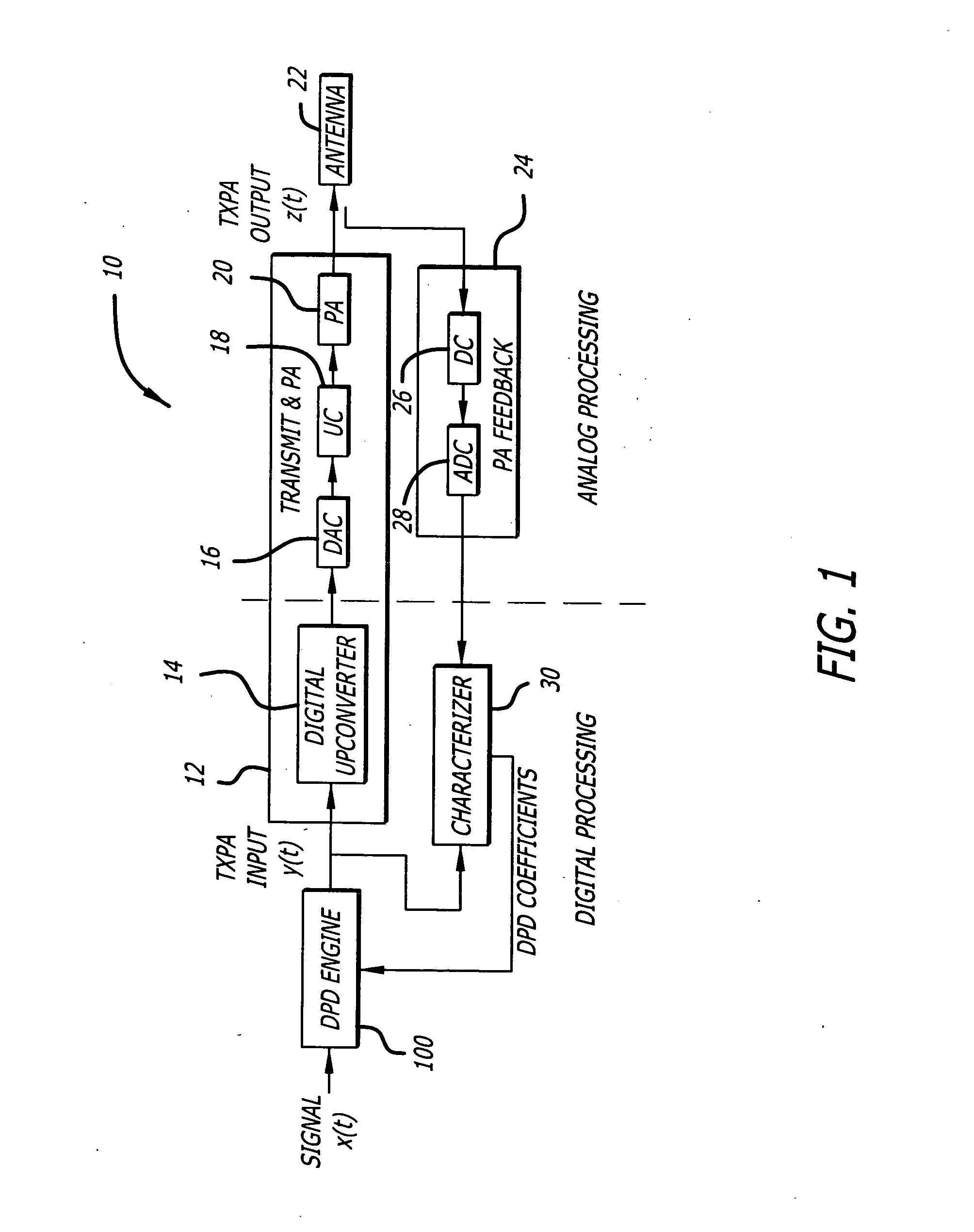
[0020]FIG. 1 is a block diagram of an illustrative implementation of a transmitter implemented in accordance with the present teachings. The inventive transmitter 10 includes a conventional transmitter 12 with a digital upconverter 14, a DAC 16, an analog upconverter (UC) 18 and a power amplifier 20. The digital upconverter 14 converts a baseband...


PUM


Abstract

A linearizer and method. In a most general embodiment, the inventive linearizer includes a characterizer coupled to an input to and an output from said circuit for generating a set of coefficients and a predistortion engine responsive to said coefficients for predistorting a signal input to said circuit such that said circuit generates a linearized output in response thereto. In a specific application, the circuit is a power amplifier into which a series of pulses are sent during an linearizer initialization mode of operation. In a specific implementation, the characterizer analyzes finite impulse responses of the amplifier in- response to the initialization pulses and calculates the coefficients for the feedback compensation filter in response thereto. In the preferred embodiment, the impulse responses are averaged with respect to a threshold to provide combined responses. In the illustrative embodiment, the combined responses are Fast Fourier Transformed, reciprocated and then inverse transformed. The data during normal operation is fed back to the data capture, corrected for distortion in the feedback path from the output of the amplifier, converted to basedband, synchronized and used to provide the coefficients for the predistortion linearization engine. As a result, in the best mode, each of the coefficients used in the predistortion linearization engine can be computed by solving the matrix equation HW=S for W, where W is a vector of the weights, S is a vector of predistortion linearization engine outputs, and H is a matrix of PA return path inputs as taught herein.

Description

BACKGROUND OF THE INVENTION [0001] 1. Field of the Invention [0002] The present invention relates to electrical and electronic circuits and systems. More specifically, the present invention relates to power amplifiers for communications systems and predistortion linearizers used in connection therewith. [0003] 2. Description of the Related Art [0004] Power amplifiers are used in a variety of communications applications. Power amplifiers not only typically exhibit non-linear distortion but also possess memory effects. While non-linear distortion follows the power amplifier characteristics, the memory effects depend on signal characteristics (e.g., signal bandwidth and also transmit power level.) [0005] Conventional techniques use Lookup Table (LUT) based methods to generate inverse transfer functions in both amplitude and phase to correct for non-linearity in the output of power amplifiers. However these techniques do not effectively handle memory effects and thus provide very modera...

Claims


Application Information

Patent Timeline
IPC IPC(8): H04L25/49
CPCH03F1/3247H03F1/3276H04L25/03885H04L25/49H04L27/2626H04L27/368
Inventor CAI, KHIEM V.RUTAN, DAVID B.GORDER, MATTHEW S.DEVENDORF, DON C.
Owner MICROELECTRONICS TECH INC
Why Eureka
Try Eureka