Electricalacoustic ransducer

Inactive Publication Date: 2006-04-13
YANG HO JOON
View PDF5 Cites 5 Cited by
  • Summary
  • Abstract
  • Description
  • Claims
  • Application Information

AI Technical Summary

Benefits of technology

[0010] It is, therefore, an objective of the present invention to provide an electrical acoustic transducer, in which a vent hole is

Problems solved by technology

However, the responsiveness and performance of the speaker system deteriorate leading to eventual failure to reproduce clear sound.
As such, the speaker system has low acoustic responsiveness and performance and fails to reproduce high-quality clear sound.
Further, in conventional headphones

Method used


Image

  • Electricalacoustic ransducer
  • Electricalacoustic ransducer
  • Electricalacoustic ransducer

Examples


first embodiment

[0040]FIG. 3 is a side cross-sectional view of a speaker according to a first embodiment of the present invention.

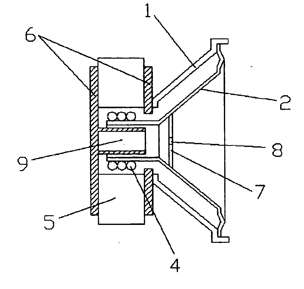
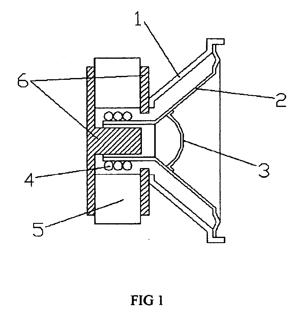
[0041] As the basic configuration of the speaker shown in FIG. 3, a frame 1 is provided with a cone 2. A voice coil 4 is assembled on a lower end of the cone 2, and a flat cap 7 is mounted in the middle of the cone 2. The present invention is not limited to the flat cap 7 as shown in FIG. 3, but may make use of a domed cap as shown in FIG. 1.

[0042] It is one of main features of the present invention that a vent hole 8 is formed in the middle of the domed or flat cap 7. It is another feature that a blind slot is formed in the middle of a yoke 6 which is located on a lower end of the frame 1, thereby acting as a resonance unit 9. Then, the yoke 6 having the resonance unit 9 is assembled with a permanent magnet 5.

[0043] Further, the slot of the resonance unit 9 is opposite to the vent hole 8.

[0044] The vent hole 8 is substantially circular in shape, whose diameter is ab...

second embodiment

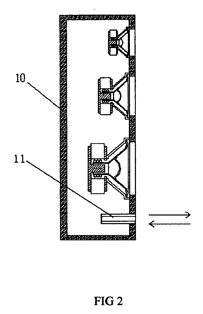
[0047]FIG. 4 is a side cross-sectional view of a speaker system according to a second embodiment of the present invention.

[0048] In FIG. 4, speakers for high-, middle-, and low-frequency sound are installed as one constituent, and cones 2 vibrate back and forth by receiving electrical signals from the outside (not shown). When the cones 2 move backward, negative pressure is generated in a resonance box 10 to thus hinder the vibration of the cones 2. In contrast, when the cones 2 move forward, positive pressure is generated in the resonance box 10 to thus hinder the vibration of the cones 2. However, as set forth in the first embodiment, the present invention employs a structure in which the flat or domed cap 7 is formed with a vent hole 8 and the resonance box 10 is provided with a damper 11.

[0049] In this manner, with the vent hole 8, the pressure generated by the closure of the resonance box 10 is processed by the damper 11, and simultaneously each speaker effectively deals with...

third embodiment

[0052]FIG. 5 is a side cross-sectional view of a speaker system according to a third embodiment of the present invention.

[0053] Each speaker of the speaker system shown in FIG. 5 performs the same function as that of the speaker system shown in FIG. 4. However, the speaker system shown in FIG. 5 is configured so that a partition 12 is provided between the speakers to define resonance boxes 13, 14 and 15 in a closed state, and each of the resonance boxes 13, 14 and 15 is provided with a damper 11 to allow each speaker to resonate according to its own characteristic.

[0054] In other words, the three speakers are used for high-, middle-, and low-frequency sound, between two of which the partitions 12 for closure are each provided to define the resonance boxes 13, 14 and 15. The resonance boxes 13, 14 and 15 resonate corresponding to the speakers respectively, and are provided with the dampers 11, 11 and 11, respectively.


PUM


Abstract

Disclosed is an electrical acoustic transducer applied to speakers, earphones, headphones, etc. The electrical acoustic transducer includes a frame having a cone, a voice coil provided on a lower end of the cone, a yoke and a permanent magnet that are provided on a lower end of the frame, a cap provided in the middle of the cone, a vent hole formed in the middle of the cap, and a resonance unit formed as a slot in the center of the yoke. The slot of the resonance unit is opposite to the vent hole. With the electrical acoustic transducer, drastic vibration of the cone is relieved by the resonance unit as well as the vent hole formed in the domed or flat cap, and thus a harsh sound is relieved. After being assembled, each speaker exerts its inherent performance to the maximum extent, so that it is possible to hear a clear and sweet sound.

Description

BACKGROUND OF THE INVENTION [0001] 1. Field of the Invention [0002] The present invention relates to an electrical acoustic transducer applied to speakers, earphones, headphones, and so on, and more specifically, to an electrical acoustic transducer with improved responsiveness and performance that reproduces high-quality clear sound. [0003] 2. Description of the Related Art [0004] In general, a speaker is configured as shown in FIG. 1. A frame 1 is provided with a cone 2. A voice coil 4 is assembled on a lower end of the cone 2. A domed cap 3 is mounted in the center of the cone 3. A yoke 6 and a permanent magnet 5 are assembled on a lower end of the frame 1. [0005] Further, a speaker system has a configuration shown in FIG. 2, where three speakers are installed in a resonance box 10 to reproduce high-, middle-, and low-frequency sound. [0006] It is fundamental that the speakers must be configured in a system in order to produce a full acoustic effect. Speaker systems can have vari...

Claims


Application Information

Patent Timeline
IPC IPC(8): H04R1/00
CPCH04R1/1008H04R1/1016H04R1/24H04R1/26H04R1/2819H04R5/033
Inventor YANG, HO-JOON
Owner YANG HO JOON
Why Eureka
Try Eureka