
Trench drain filter assembly

Active Publication Date: 2006-04-13
OLDCASTLE PRECAST
View PDF10 Cites 22 Cited by
  • Summary
  • Abstract
  • Description
  • Claims
  • Application Information

AI Technical Summary

Benefits of technology

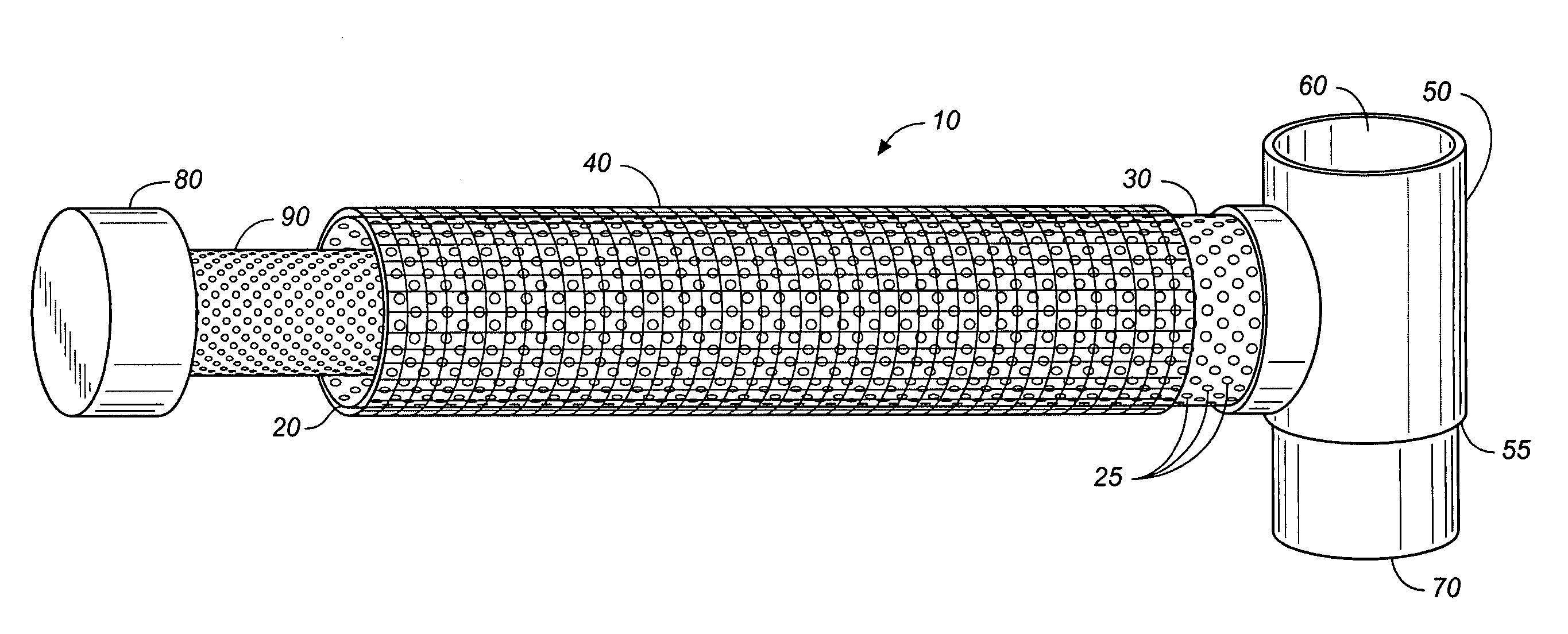
[0010] The present invention is an improved, low cost, easy to install elongate filter for trench drains which does not require the use of a cradle to support a filter medium. Instead, the filter apparatus of the present invention comprises a hollow, elongate tubular support structure which is connected at its one end to the outlet of the trench drain. The structure is made sufficiently porous such that first, low volume flows entering the trench drain must pass through and within to the interior of the structure before entering the drainage discharge. An overflow bypass is provided such that during times of high water flow, backed up water may pass directly to the drain discharge, thus assuring that the capacity of the drain is not compromised by the presence of the drain filter.
[0015] It is another object of the present invention to provide a trench drain filter apparatus that is easy and inexpensive to install in existing drain water systems.

Problems solved by technology

These contaminants are either carried by the drainage systems to treatment plants where their introduction increases the load on the plant's purification systems, or they are directly discharged to the environment, that is onto land or into streams, lakes and other bodies of water in an untreated state, such untreated water further stressing the environment.
This product is expensive to manufacture, however, due to the need to custom size the elongate cradle to the trench drain being fitted, and, due to the requirement it be non corrosive, the cradle is made from stainless steel.
The sizing requirement can be particularly problematic where the trench to be fitted is both narrow and shallow, e.g. five inches wide by five to six inches deep, and must accommodate both the cradle, and filter bag, and still receive the cover grating.
Furthermore, the FloGard™ (absorbent bag) inserts used with this product are currently provided in two foot sections, the use of such short sections increasing the time required for installation, and maintenance, especially given the extended lengths of some trench drains, which can be as long as 50 feet, or more.

Method used


Image

  • Trench drain filter assembly
  • Trench drain filter assembly
  • Trench drain filter assembly

Examples


Embodiment Construction

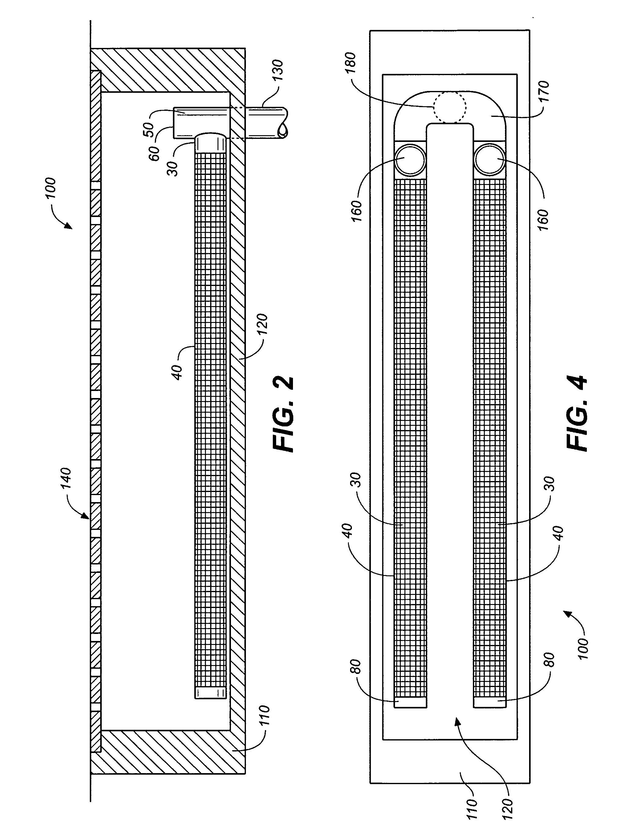
[0030] The trench drain filter apparatus of the present invention comprises an outer, porous, elongate, corrosion resistant support structure which can be formed of any rigid or semi-rigid material, the support structure defining an inner compartment into which is placed a pouch or pouches containing absorbent material. The support structure of the apparatus is preferably tubular, and the entire assembly is preferably provided in modular form, wherein a plurality of filter elements are disposed between two or more flow control baffles in an enclosure configured to direct waste water through the filter elements.

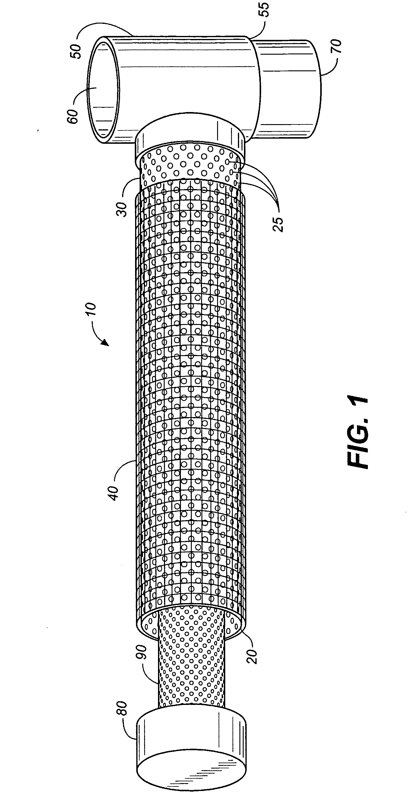
[0031] Referring now to FIGS. 1-7, wherein like numbers refer to like elements in the various views, FIG. 1 shows a first preferred embodiment of the inventive trench drain filter of the present invention, generally denominated 10 herein. This view shows the inventive trench drain filter as comprising an elongate, corrosion resistant tube or support structure 20 formed from a...


PUM

PropertyMeasurementUnit
Lengthaaaaaaaaaa
Porosityaaaaaaaaaa
Water absorptionaaaaaaaaaa

Abstract

An improved trench drain filter and modular system therefor for intercepting and treating run off water in a trench drain before discharge into a drainage system. The filter elements include a perforated pipe covered with one or more layers of geotextile material, which is, in turn, covered with a permeable fabric membrane. In a preferred embodiment a pouch containing an absorbent agent is disposed within the pipe upstream of the discharge point, and in another embodiment a multi-filter modular unit is provided, the unit including a plurality of filter elements disposed in an enclosure having fluid flow control baffles to direct fluid to and through the filter elements.

Description

CROSS REFERENCE TO RELATED APPLICATIONS [0001] The present application claims the benefit of the filing date of U.S. Provisional Patent Application Ser. No. 60 / 617,885, filed Oct. 12, 2004 (Oct. 12, 2004), and U.S. Provisional Patent Application Ser. No. [TBA], entitled, Improved Trench Drain Filter Assembly, filed Oct. 5, 2005.STATEMENT REGARDING FEDERALLY SPONSORED RESEARCH OR DEVELOPMENT [0002] Not applicable. REFERENCE TO A MICROFICHE APPENDIX [0003] Not applicable. TECHNICAL FIELD [0004] The present invention generally relates to an apparatus for treating surface water runoff prior to its discharge into a drainage system, and more particularly to a modular filter and filter assembly for use in trench drains. BACKGROUND INFORMATION AND DISCUSSION OF RELATED ART [0005] Of continuing concern today is untreated run off from streets, highways, parking lots, loading areas and the like, where leaked hydrocarbons, such as gasoline, diesel oils, lubricating oils, rubber and metal partic...

Claims


Application Information

Patent Timeline
IPC IPC(8): E02B11/00
CPCB01D29/54B01D35/02E02B11/005E03F1/00E03F5/0404B01D29/58
Inventor ALLARD, DOUGLAS PAULMCDONALD, JONATHAN
Owner OLDCASTLE PRECAST
Learn More