
Subsea gang connector system

Active Publication Date: 2006-04-13
OCEANWORKS INT
View PDF5 Cites 40 Cited by
  • Summary
  • Abstract
  • Description
  • Claims
  • Application Information

AI Technical Summary

Benefits of technology

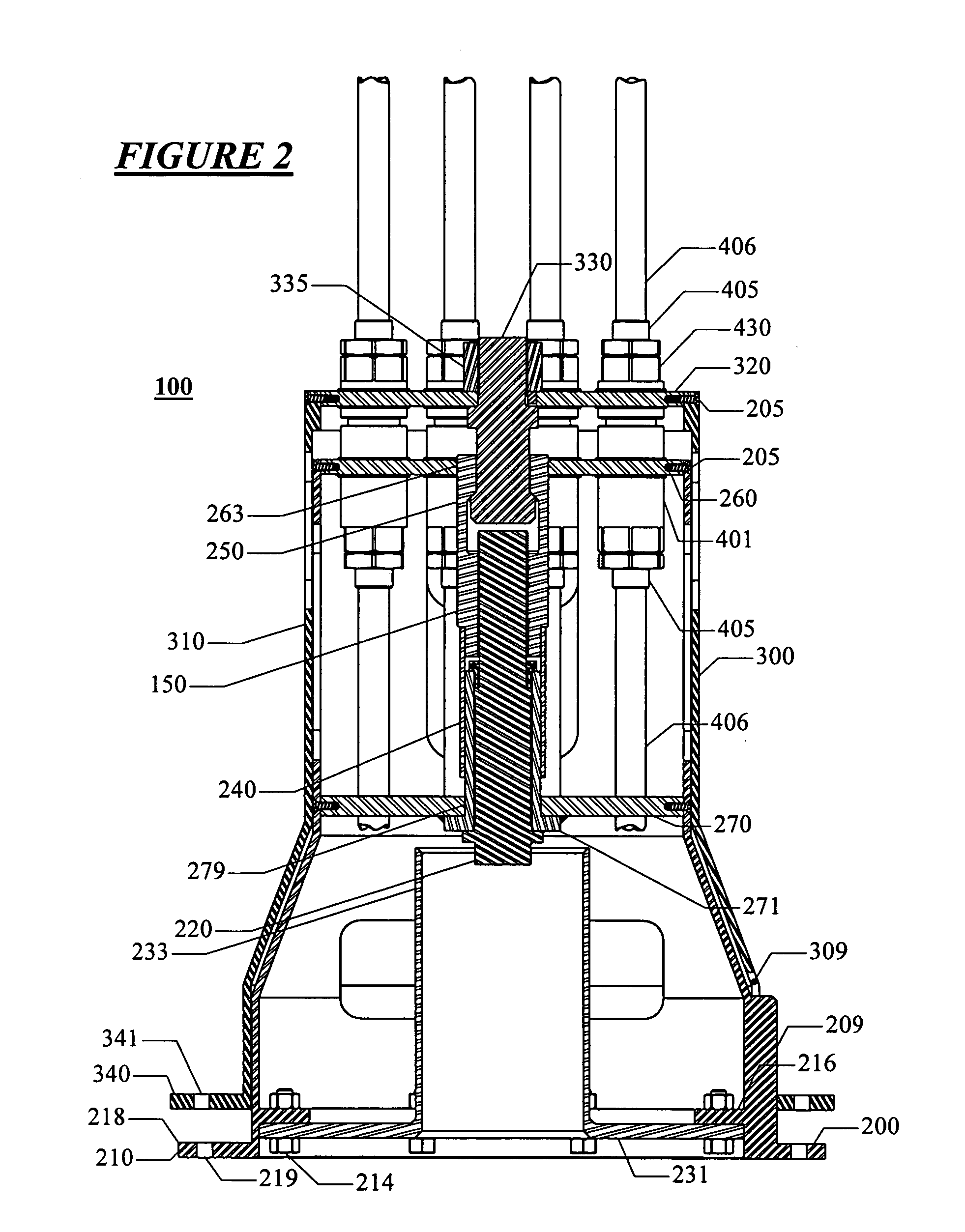
[0020] One aspect of the present invention is a selectably engagable and disengagable subsea connector system for mating a plurality of mutually comateable male and female couplers located within fixed and removable connectors of a subsea connector system to provide a plurality of sealed conduits. The removable connector has a housing connected to a transverse end plate. The female couplers are mounted on and extend outwardly from the removable end plate. The fixed connector has a housing connected to a second transverse end plate. The male couplers extend inwardly from the fixed end plate. The removable housing and the fixed housing have similar geometric properties such that they are mutually engagable and thereby assist the alignment of the removable connector within the fixed connector to facilitate the subsea engagement of the plurality of male and female couplers to form a plurality of sealed conduits.

Problems solved by technology

Due to operational conditions (such as ROV size and strength, weight of connectors, ocean currents and drag induced by pulling the cables across the seafloor), proper alignment of the removable and fixed connectors can be difficult and time consuming, and improper alignment can damage the components of the fixed and / or removable connectors.
This concept is compact and works well to pull the halves together but when the operation takes place in deep water where the force to separate the plates is large, the fingers of the collet are susceptible to buckling.
A disadvantage to this concept is that the size of the receptacle used in the connector relative to the thread size is not very efficient for designs concerned with size and weight.
This design leaves the latch pin exposed to damage from storage, handling, transport and installation of the removable connector.
All of the above-described designs leave the tubing exposed to damage from handling and ROV operations, are susceptible to thread damage and are difficult to align, thereby increasing the probability of damaged tubing or other components during installation.

Method used


Image

  • Subsea gang connector system
  • Subsea gang connector system
  • Subsea gang connector system

Examples


Embodiment Construction

[0041] The present invention provides a rapid, reliable and accurate process for remotely making secure hydraulic gang connections in difficult environments and under hazardous conditions.

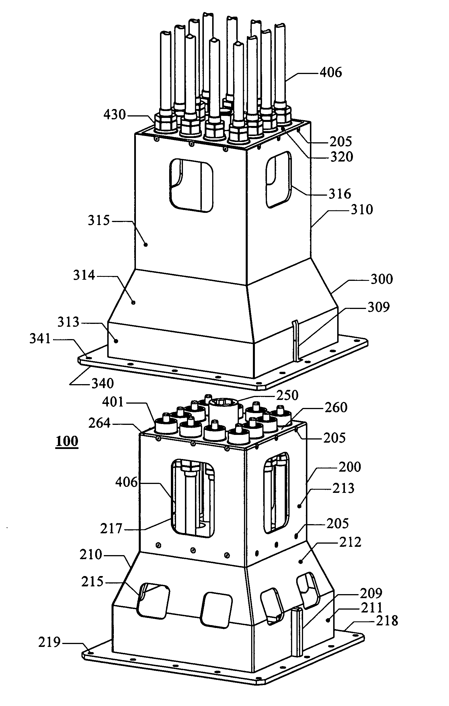
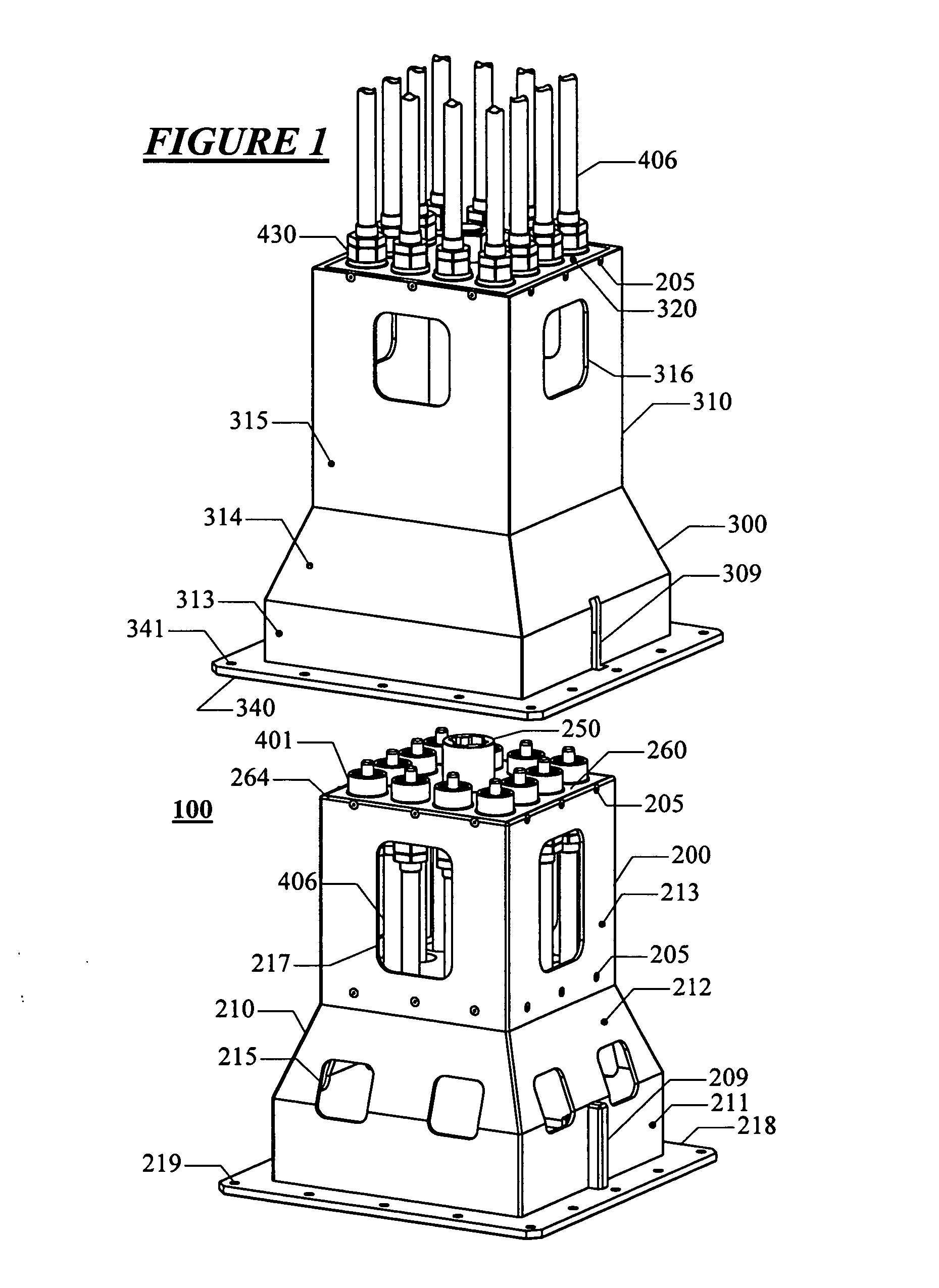
[0042] As shown in FIG. 1, one preferred embodiment of the present invention is a subsea connector system 100 used for subsea connection of removable and fixed-mounted couplings for hydraulics, as shown herein, but also for electrical lines, fiber optics, process fluids and other components that require sealed conduits.

[0043] The subsea connector system 100 consists of two major components: a removable (outboard) connector 200 and a fixed (inboard) connector 300 that can be connected to each other in any orientation. The subsea connector system 100 is especially applicable for use with stiff cables and bundles of tubes that are difficult to align subsea with ROVs.

[0044] For ease of understanding, all examples and drawings assume a vertical orientation with the fixed connector the upper connector...


PUM


Abstract

A subsea connector system is used to connect internally mounted couplers to provide sealed conduits for subsea operations. The system has a removable (outboard) connector and a fixed (inboard) connector each with a housing having special geometric properties that facilitate alignment and connection of the couplers. The latching mechanism has a latch pin in the fixed connector and a latch sleeve in the removable connector for receiving and latching to the latch pin. The couplers (male and female) and the latching mechanism are located within the housings of the fixed and removable connectors to provide protection for the components from damage during storage, handling, transport and installation operations.

Description

CROSS REFERENCE TO RELATED APPLICATIONS [0001] The present application, pursuant to 35 U.S.C. 111(b), claims the benefit of the filing date of provisional application Ser. No. 60 / 616,803 filed Oct. 7, 2004, and entitled “Subsea Connector.”BACKGROUND OF THE INVENTION [0002] 1. Field of the Invention [0003] The present invention relates in general to a method and apparatus for making secure a hydraulic gang connector in remote or hazardous locations. More particularly, the invention relates to a method and apparatus for the simultaneous connection and disconnection of multiple male and female couplers to provide sealed conduits for subsea operations. [0004] 2. Description of the Related Art [0005] Subsea oil and gas production equipment that requires the use of external signals or the supply of fluids for operation is normally connected subsea after installation with interconnecting cables, jumpers, or umbilicals having removable connectors on each end. Remotely Operated Vehicles (“RO...

Claims


Application Information

Patent Timeline
IPC IPC(8): H01R13/52
CPCF16L1/10F16L39/00H01R13/523H01R13/6277H01R13/2421H01R13/629H01R2107/00
Inventor ALLENSWORTH, DAVID CARTERCROWN, TIMOTHY WILLIAM
Owner OCEANWORKS INT
Learn More