Powerhead control in a power injection system

Active Publication Date: 2006-04-13
LIEBEL FLARSHEIM CO
View PDF30 Cites 145 Cited by
  • Summary
  • Abstract
  • Description
  • Claims
  • Application Information

AI Technical Summary

Benefits of technology

[0020] It will be appreciated that both the test injection and patency check have common characteristics that distinguish them from normal programming of an injector. Specifically, both are an injection that is separately enabled from the stored injection protocol to be administered to the patient, and both are separate from the stored injection protocol, i.e., they may selectively be conducted, or not, at the operator's discretion. Thus, the operator need not perform a patency check or test injection, but has the ready option to do so without altering a stored injection protocol. While the patency check and test injection are thus functionally and operationally separated from a stored protocol, they are nevertheless programmatically controlled injections, and use parameters that may be derived from the later, stored injection protocol, e.g., the flow rates or use of fluids is modeled after the planned injection. Because the test injection and patency check are programmatically controlled injections, they may accurately mimic the stored injection protocol in the relevant aspects, without the effort of human involvement and the possibility for human error. Furthermore, because they are programmatically controlled, it is possible to calculate the fluid requi

Problems solved by technology

Nevertheless, the potential for accidentally injecting air into a patient remains a serious safety concern.
Unfortunately, operators have found it cumbersome to use the hand-operated movement buttons and to read the injector head gauges and displays, for several reasons, not the least of which is the necessary tilting of the injector head between the upward, filling position to

Method used


Image

  • Powerhead control in a power injection system
  • Powerhead control in a power injection system
  • Powerhead control in a power injection system

Examples


Embodiment Construction

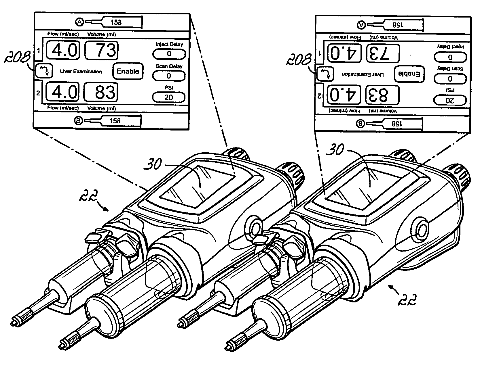
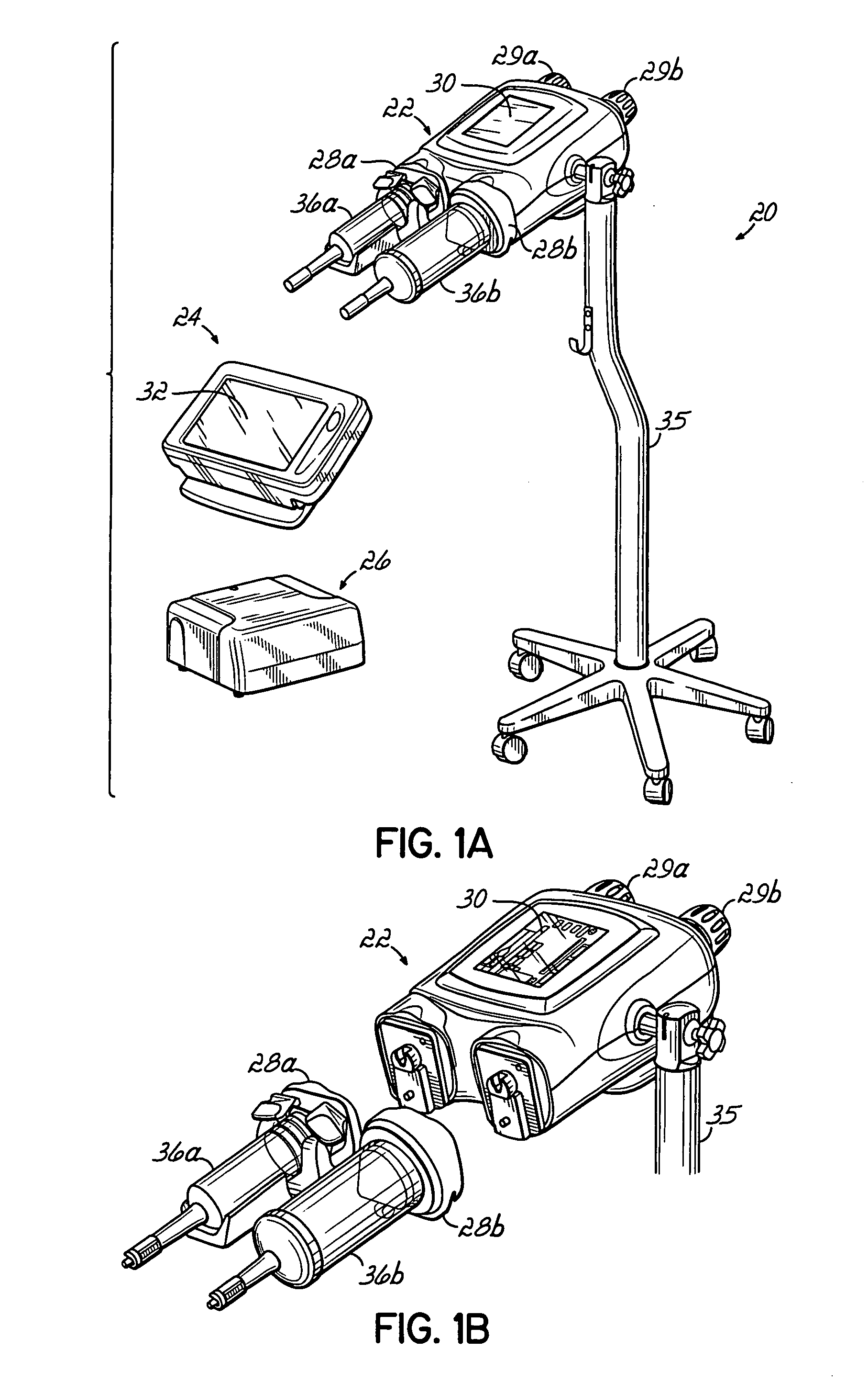
[0040] Referring to FIG. 1A, an injector 20 in accordance with the present invention includes various functional components, such as a powerhead 22, a console 24 and powerpack 26. Syringes 36a and 36b are mounted to the injector 20 in faceplates 28a and 28b of the powerhead 22, and the various injector controls are used to fill the syringe with, e.g., contrast media for a CT, Angiographic or other procedure, which media is then injected into a subject under investigation under operator or pre-programmed control.

[0041] The injector powerhead 22 includes a hand-operated knobs 29a and 29b for use in controlling the movement of the internal drive motors engaged to syringes 36a and 36b, and a display 30 for indicating to the operator the current status and operating parameters of the injector. The console 24 includes a touch screen display 32 which may be used by the operator to remotely control operation of the injector 20, and may also be used to specify and store programs for automat...


PUM


Abstract

A dual head contrast media injection system performs a patency check or test injection, determining flow rate and/or flow volume from the programmed protocol. The tubing that connects syringes to a patient shares only a short common section near to the patient. Appropriate injection steps are taken to compensate for tubing elasticity. A wireless remote control and a touch screen control are provided, improving functionality and information delivery. The display brightness is controlled based on the ambient light, and the display panel includes a double swivel permitting re-orientation. The orientation of the display may also be controlled based on, e.g., the current step, the tilt angle of the powerhead, or a manual control. Furthermore, the display is customizable to identify the type of fluid (contrast, saline, etc.) on either side of the injector, to provide matched color coding, and to provide a folder/tab analogy for retrieving injection protocol parameters.

Description

CROSS REFERENCE TO RELATED APPLICATIONS [0001] The present application is a divisional application of U.S. application Ser. No. 10 / 964,002, filed Oct. 13, 2005, entitled POWERHEAD OF A POWER INJECTION SYSTEM, which is related to co-pending application Ser. No. 10 / 964,003, filed Oct. 13, 2005, entitled POWERHEAD OF A POWER INJECTION SYSTEM. The present application is related to co-pending and concurrently filed application Ser. No. ______, entitled POWERHEAD OF A POWER INJECTION SYSTEM and the two divisional applications of application Ser. No. 10 / 964,003, filed Oct. 13, 2005, entitled POWERHEAD OF A POWER INJECTION SYSTEM. All of these applications are hereby incorporated by reference herein in their entirety. FIELD OF THE INVENTION [0002] The present invention relates to contrast media injector systems and, more particularly to improvements thereto. BACKGROUND OF THE INVENTION [0003] In many medical environments, a medical fluid is injected into a patient during diagnosis or treatm...

Claims


Application Information

Patent Timeline
IPC IPC(8): A61M5/00
CPCA61M5/007A61M5/14546A61M5/14566A61M5/16827A61M5/172A61M39/10A61M2205/3362A61M2205/3523A61M2205/3561A61M2205/3592A61M2205/50A61M2205/505A61M2205/6081
Inventor SMALL, JAMES R.BROOKS, DAVID M.NEER, CHARLES S.FAGO, FRANK M.
Owner LIEBEL FLARSHEIM CO
Why Eureka
Try Eureka