

Ultrasonic imaging apparatus
- Summary
- Abstract
- Description
- Claims
- Application Information
AI Technical Summary
Benefits of technology
Problems solved by technology
Method used
Image

Examples
first embodiment
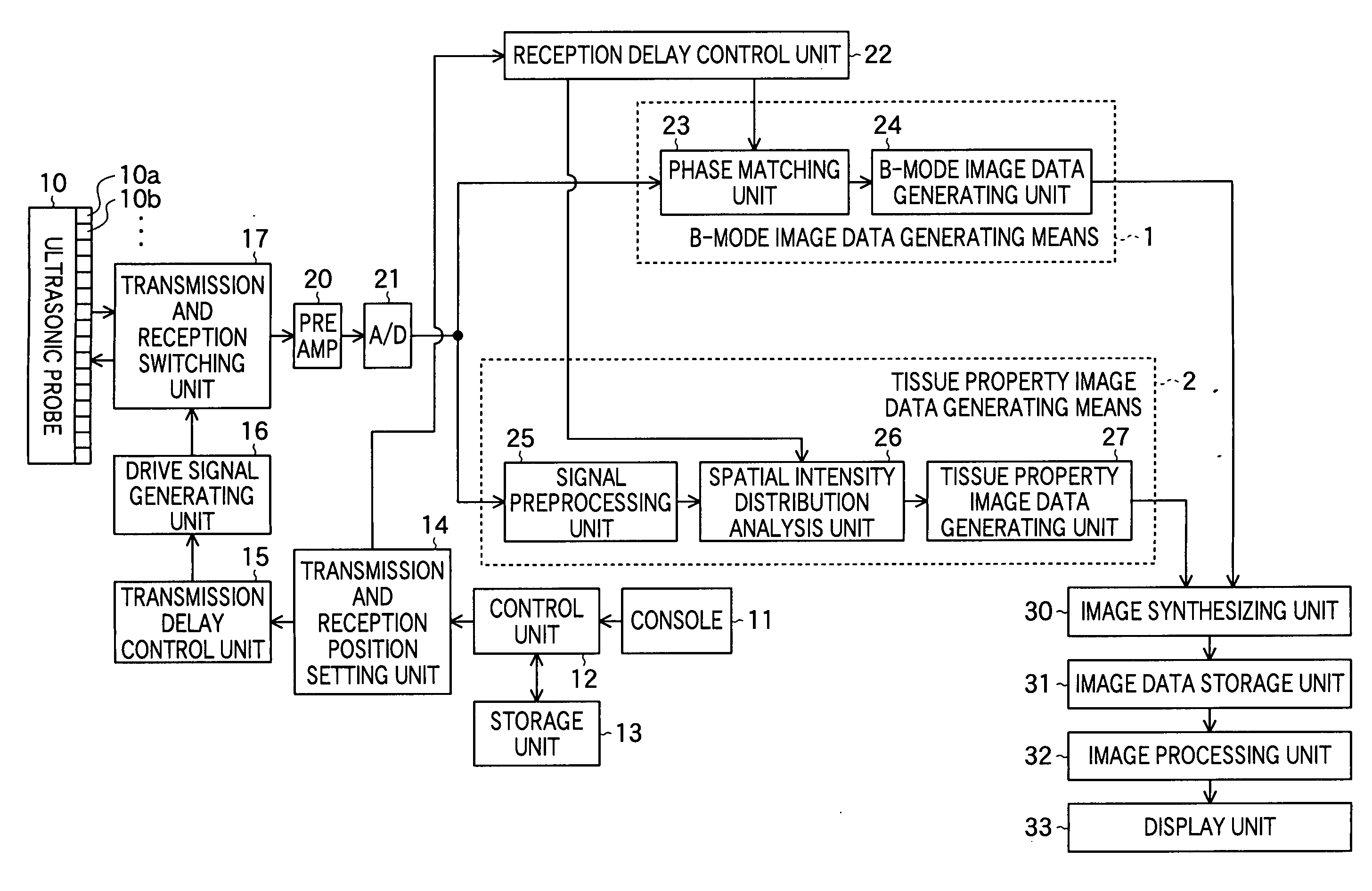
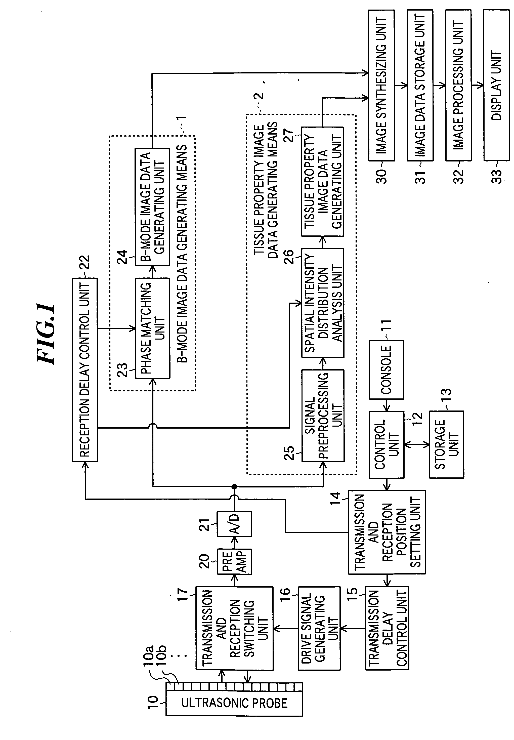
[0043]FIG. 1 is a block diagram showing a constitution of an ultrasonic imaging apparatus according to the present invention. The ultrasonic imaging apparatus according to the embodiment includes an ultrasonic probe 10, a console 11, a control unit 12, a storage unit 13, a transmission and reception position setting unit 14, a transmission delay control unit 15, a drive signal generating unit 16, and a transmission and reception switching unit 17.
[0044] The ultrasonic probe 10 is used by being abutted on an object to be inspected to transmit ultrasonic waves to the object and receive ultrasonic waves reflected from the object. The ultrasonic probe 10 includes plural ultrasonic transducers 10a, 10b, . . . for transmitting ultrasonic beams based on applied drive signals, receiving propagating ultrasonic echoes to output reception signals. These ultrasonic transducers 10a, 10b, . . . are arranged in a one-dimensional or two-dimensional manner to form a transducer array.
[0045] Each ult...
second embodiment
[0106] Next, an ultrasonic imaging apparatus according to the present invention will be described. FIG. 9 is a block diagram showing the constitution of the ultrasonic imaging apparatus according to the embodiment.
[0107] As shown in FIG. 9, this ultrasonic imaging apparatus further has a reflectance correction unit 40 as compared to the ultrasonic imaging apparatus shown in FIG. 1. Other constitution is the same as that of the ultrasonic imaging apparatus shown in FIG. 1.
[0108] The reflectance correction unit 40 utilizes statistics values calculated by the spatial intensity distribution analysis unit 26 as parameters to provide amounts of correction for correcting B-mode image data to the B-mode image data generating unit 24.
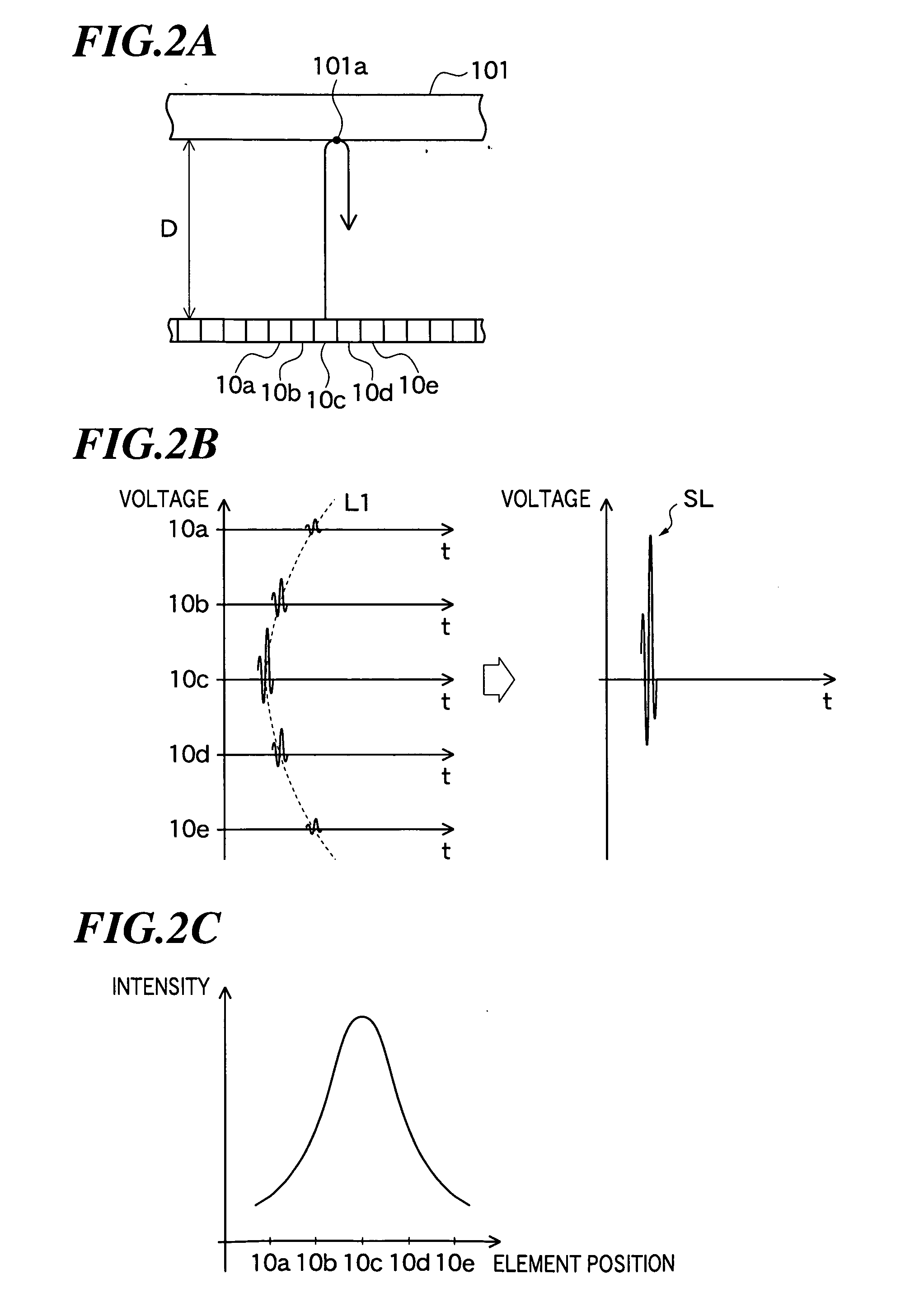
[0109] Here, referring FIGS. 2A and 4A again, a case will be considered where ultrasonic beams with the same intensity are transmitted to specular reflectors 101 and 103 having the same surface property. As shown in FIG. 4A, when the specular reflector 103 is ...
third embodiment
[0114] Next, an ultrasonic imaging apparatus according to the present invention will be described. FIG. 10 is a block diagram showing the constitution of the ultrasonic imaging apparatus according to the embodiment.
[0115] As shown in FIG. 10, this ultrasonic imaging apparatus has tissue property image data generating means 3 in place of the tissue property image data generating means 2 in the ultrasonic imaging apparatus shown in FIG. 1. Other constitution is the same as that of the ultrasonic imaging apparatus shown in FIG. 1.
[0116] The tissue property image data generating means 3 has a signal preprocessing unit 25, a histogram analysis unit 50, and a tissue property image data generating unit 51. The histogram analysis unit 50 generates a histogram based on plural reception signals on the same phase matching line of the plural reception signals that have been intensity corrected by the signal preprocessing unit 25, and thereby, calculates statistics values representing tissue pr...
PUM
 Abstract
Description
Claims
Application Information