Storage apparatus
- Summary
- Abstract
- Description
- Claims
- Application Information
AI Technical Summary
Benefits of technology
Problems solved by technology
Method used
Image

Examples
first embodiment
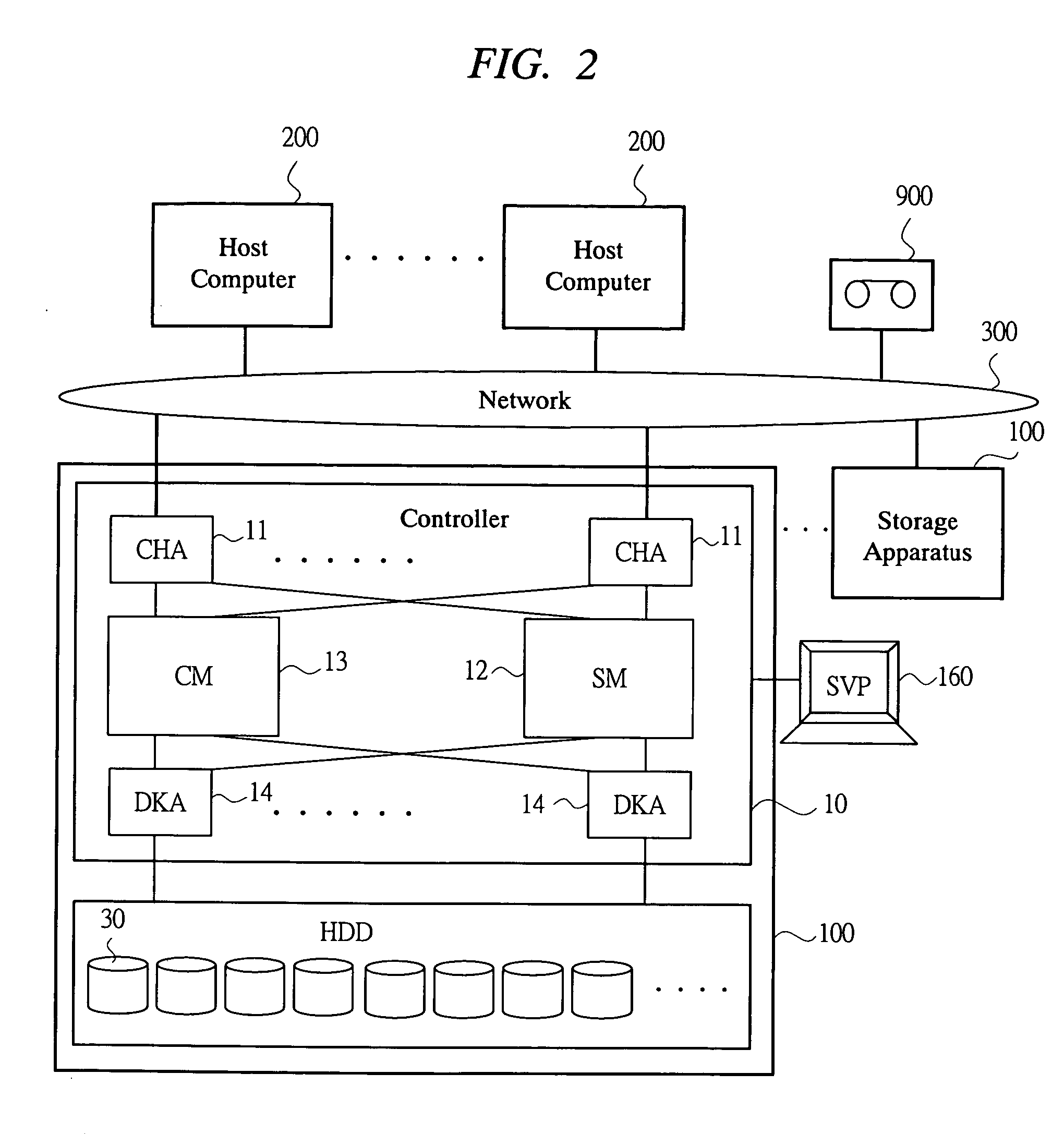
[0050] FIGS. 1 to 16 are diagrams for explaining a storage apparatus according to a first embodiment of the present invention. The first embodiment includes a device mounting means in a computer system to which a host and a storage apparatus are connected, handles a virtual device on a side of a host, and shows a basic configuration and process of a device mounting method in which the actual device handled in the storage apparatus is mounted on and accessed to the virtual device as occasion demands. The host side has few pieces of I / O configuration information (virtual device address) than a side of the storage apparatus. Note that processes relating to a device mounting shown in each embodiment are independent from a process for mounting a magnetic tape in a conventional magnetic tape unit.
[0051]
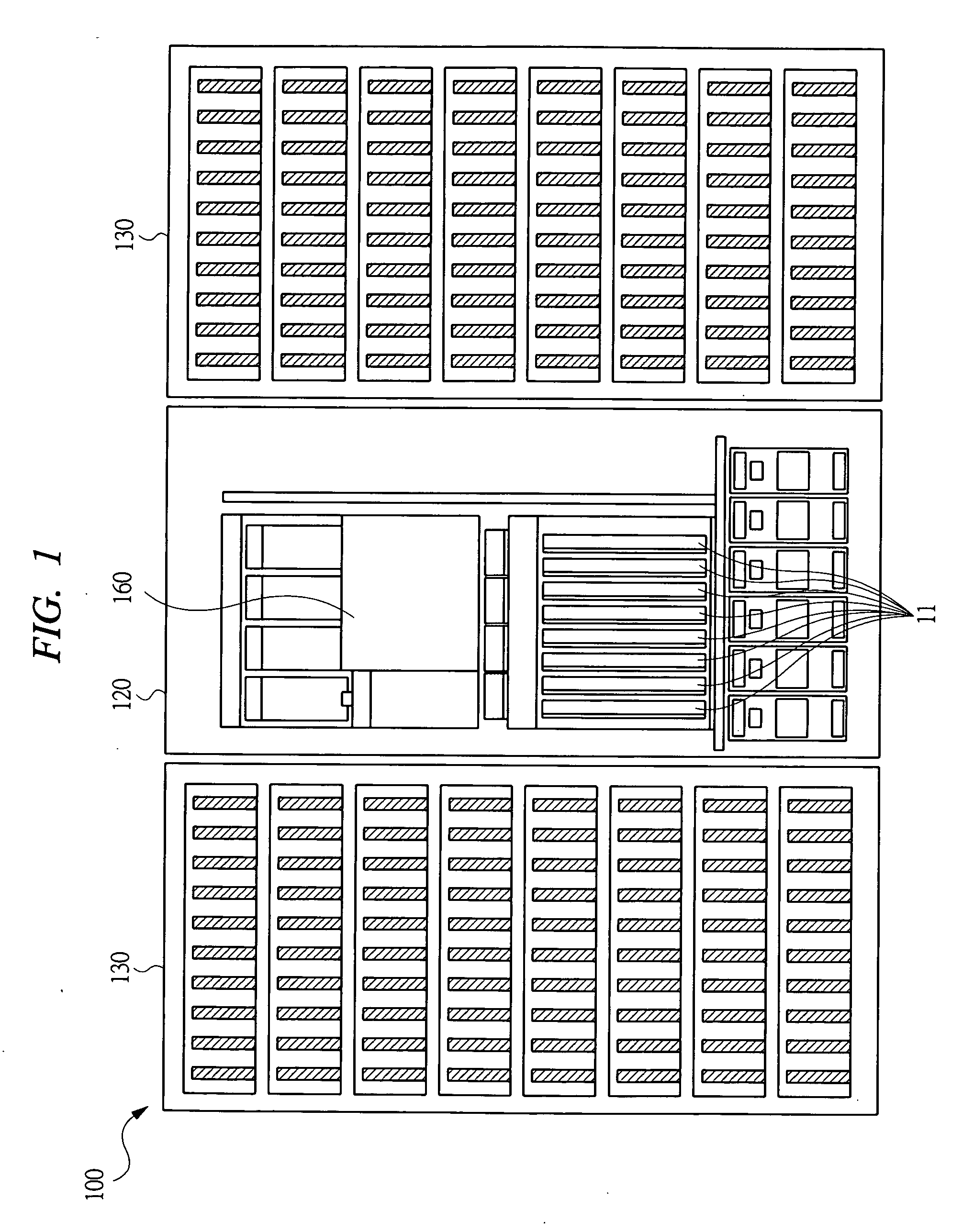
[0052] First, the entire configuration of the storage apparatus of the first embodiment will be explained. Then, a characteristic process of the present invention will be explained. FIG. 1...
second embodiment
[0141]
[0142] Next, in addition to the configuration of the first embodiment, a storage apparatus according to a second embodiment of the present invention executes generation management of a virtual device to be an object. The hardware configuration thereof is the same as that of the first embodiment. FIG. 17 is an explanatory diagram of a device mounting method employed in a storage apparatus of a second embodiment. The generation management performs, on the side of the storage apparatus 100, a process for saving and controlling a data-state change due to temporal elapse of the same virtual data so as to be handled as data of the actual device of each generation, whereby the data of each generation, which are different in the access to the same virtual device address 23 from the side of the host 200, becomes available. An opportunity of saving the generation includes, for example, a periodical timing, a timing at which a condition setting such as data update is performed, and a tim...
third embodiment
[0147]
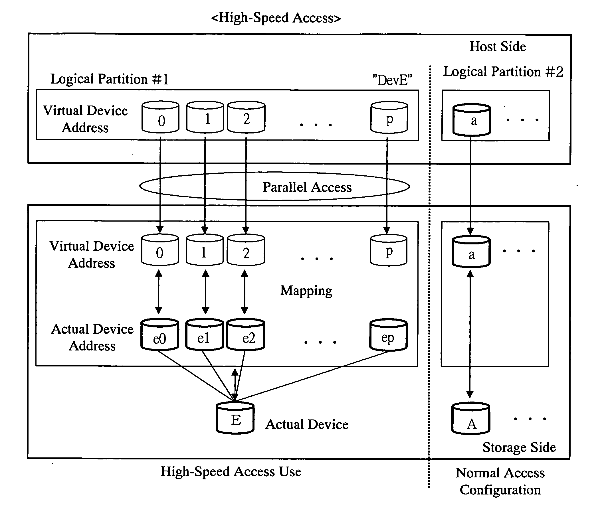
[0148] Next, a storage apparatus according to a third embodiment of the present invention has the configuration of the first embodiment and further sets logical partitions of the virtual devices to be objects, thereby making a use dedicated etc. to the virtual devices corresponding to the logical partitions. The hardware configuration thereof is the same as that of the first embodiment. FIG. 19 is an explanatory diagram of a device mounting method employed in the storage apparatus of the third embodiment.
[0149] By setting the logical partitions on the side of the host 200, resources such as processors of the host 200 are used by partitioning. The configuration is made so that the I / O configuration information corresponding to each of the logical partitions is retained on the side of the host 200, and the devices to be processing objects by each logical partition are set. The command processes or the like are the same as those in the above-described embodiments. Accordingly, d...
PUM
 Abstract
Description
Claims
Application Information
 - Generate Ideas
- Intellectual Property
- Life Sciences
- Materials
- Tech Scout
- Unparalleled Data Quality
- Higher Quality Content
- 60% Fewer Hallucinations
Browse by: Latest US Patents, China's latest patents, Technical Efficacy Thesaurus, Application Domain, Technology Topic, Popular Technical Reports.
© 2025 PatSnap. All rights reserved.Legal|Privacy policy|Modern Slavery Act Transparency Statement|Sitemap|About US| Contact US: help@patsnap.com