Patient oxygen delivery mask

a technology for oxygen masks and patients, applied in the field of new oxygen masks, can solve the problems of only being used for oxygen masks, and unable to provide oxygen to patients

Inactive Publication Date: 2006-04-20
SOUTHMEDIC
View PDF30 Cites 48 Cited by
  • Summary
  • Abstract
  • Description
  • Claims
  • Application Information

AI Technical Summary

Benefits of technology

[0012] In a further embodiment of the present invention, the mask additionally includes the oxygen delivery tube. It is releasably securable to the outer surface of the central portion of the mask so as to communicate with the oxygen delivery aperture. As well, a baffle is provided, the baffle being constructed so as to be releasably seated over the oxygen delivery aperture on the inner surface of the central portion of the mask. The inner surface of the baffle is configured so as to assist, during use of the mask, in creating turbulence in an oxygen flow leaving the oxygen delivery aperture and assist in mixing oxygen with ambient air and thereby avoid a direct flow of oxygen towards the patient's face.
[0013] In a yet a further embodiment of the present invention, the mask is further provided with an oxygen/carbon dioxide monitor tube releasably securab...

Problems solved by technology

Many problems exist with such masks, including the fact that many patients find them claustrophobic, the mask must be removed for the patient to speak or eat, thereby discontinuing therapy, and the face mask creates irregular and inefficient infusion of oxygen by the patient since exhaled air from the patient is mixed with oxygen in the mask.
Oxygen masks can only be used for oxygen flows greater than 4 litres/minute because exhaled gas accumulates in the mask, and, at lower flow rates interferes with delivery of oxygen-enriched air to the patient.
The oxygen delivery tube and nasal cannulae are supported in position by a tube wrapped about the patient's ears or head...

Method used


Image

  • Patient oxygen delivery mask
  • Patient oxygen delivery mask
  • Patient oxygen delivery mask

Examples


Embodiment Construction

[0023] In the following description similar features in the drawings have been given similar reference numerals.

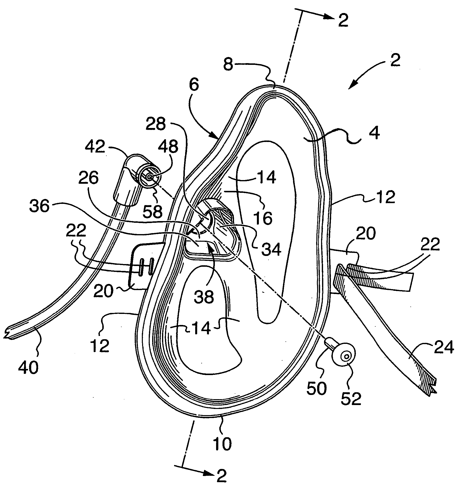
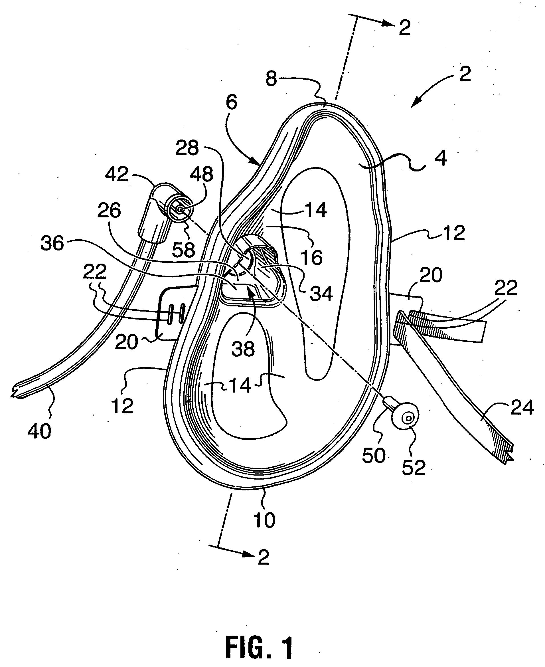
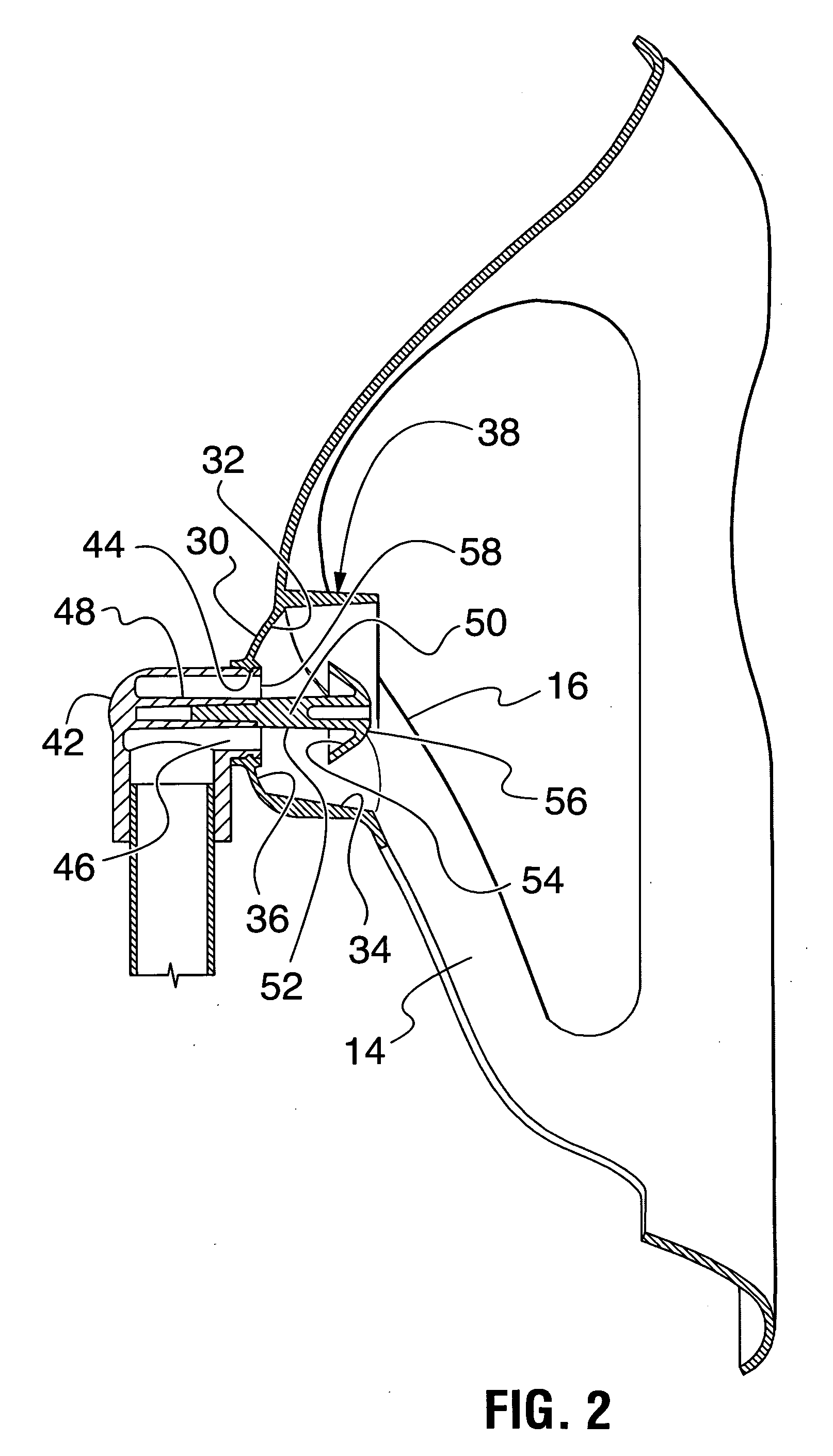
[0024] Turning to FIGS. 1 and 2 there is illustrated an oxygen delivery mask 2 in accordance with the present invention. Mask 2 is made up of a body 4 having a peripheral portion 6 with a top 8 and a bottom 10. Sides 12 extend between top 8 and bottom 10. As can be seen in FIG. 3, peripheral portion 6, when mask 2 is in use, rests on portions of a user's face both above the user's nose (top 8) and on the user's chin (bottom 10). Integrally formed with peripheral portion 6 are bridge portions 14 which integrally connect with a central portion 16. Bridge portions 14 and central portion 16 have an inverted “Y” shaped configuration (from top to bottom of the mask), when viewed from the front (FIG. 5), providing unobstructed access to and viewing of the patient's mouth and other parts of the patient's face, so that for example, the patient may eat and drink without removing th...


PUM


Abstract

A mask for delivery of oxygen to a patient, comprising a body having a peripheral portion to sit comfortably on a patient's face, a central portion, and bridge portions extending between the central portion and the peripheral portion and integral therewith, the central portion having an inner surface and an outer surface, the inner surface oriented towards the patient's face and spaced over the patient's nose and mouth, the inner surface of the central portion including a wall circumscribing a base, the wall and base being of generally concave configuration and circumscribing a centrally positioned oxygen delivery aperture extending through the central portion, the wall and base configured so as to act as an oxygen diffuser to direct the flow of oxygen generally towards the patient's nose and mouth when the mask is in use.

Description

FIELD OF THE INVENTION [0001] The present invention relates to a novel mask for delivery of oxygen to a patient, and more particularly to a mask which can be used to replace conventional oxygen masks and nasal cannulae oxygen delivery systems. BACKGROUND OF THE INVENTION [0002] Conventional oxygen masks comprise tent like structures which are strapped over the nose and mouth of the patient, often using an elastic band or bands behind the patient's ears or head. Oxygen is fed from a supply through a tube into the bottom portion of the mask at the front of the patient. Many problems exist with such masks, including the fact that many patients find them claustrophobic, the mask must be removed for the patient to speak or eat, thereby discontinuing therapy, and the face mask creates irregular and inefficient infusion of oxygen by the patient since exhaled air from the patient is mixed with oxygen in the mask. Oxygen masks can only be used for oxygen flows greater than 4 litres / minute be...

Claims


Application Information

Patent Timeline
IPC IPC(8): A62B18/02A62B23/02
CPCA61M16/06A61M16/0816A61M2202/0208A61M2230/432A61M16/085
Inventor MCDONALD, LEE
Owner SOUTHMEDIC
Why Eureka
Try Eureka