Laser induced thermal imaging (LITI) apparatus

a technology of laser induced thermal imaging and liti apparatus, which is applied in the direction of manufacturing tools, transportation and packaging, packaging, etc., can solve the problems of difficult to attach a large-sized roller system to a liti apparatus, and complicated roller systems

Inactive Publication Date: 2006-04-20
SAMSUNG DISPLAY CO LTD
View PDF23 Cites 20 Cited by
  • Summary
  • Abstract
  • Description
  • Claims
  • Application Information

AI Technical Summary

Benefits of technology

[0010] The chuck can further include at least one second lower ventilation hole, which is disposed around the lower substrate and enables the adhesion of the upper substrate to the lower substrate or the detachment of the upper substrate from the lower substrate. Thus, the upper substrate can be further adhered to the lower substrate. After irradiating the laser beam, the upper substrate can be easily detached from the lower substrate.
[0011] The cap can further include a second upper ventilation hole for attracting the upper substrate toward the cap. Because a transfer layer of the upper substrate can be out of contact with the lower substrate, it can be freed from damage caused by contact.

Problems solved by technology

Furthermore, it is difficult for a complicated and large-sized roller system to be attached to an LITI apparatus.

Method used


Image

  • Laser induced thermal imaging (LITI) apparatus
  • Laser induced thermal imaging (LITI) apparatus
  • Laser induced thermal imaging (LITI) apparatus

Examples


Embodiment Construction

[0025] The present invention will now be described more fully hereinafter with reference to the accompanying drawings, in which exemplary embodiments of the invention are shown. This invention can, however, be embodied in different forms and should not be construed as being limited to the embodiments set forth herein. It will also be understood that when a layer is referred to as being “on” another layer or substrate, it can be directly on the other layer or substrate or intervening layers can also be present. The same reference numerals are used to denote the same elements throughout the specification.

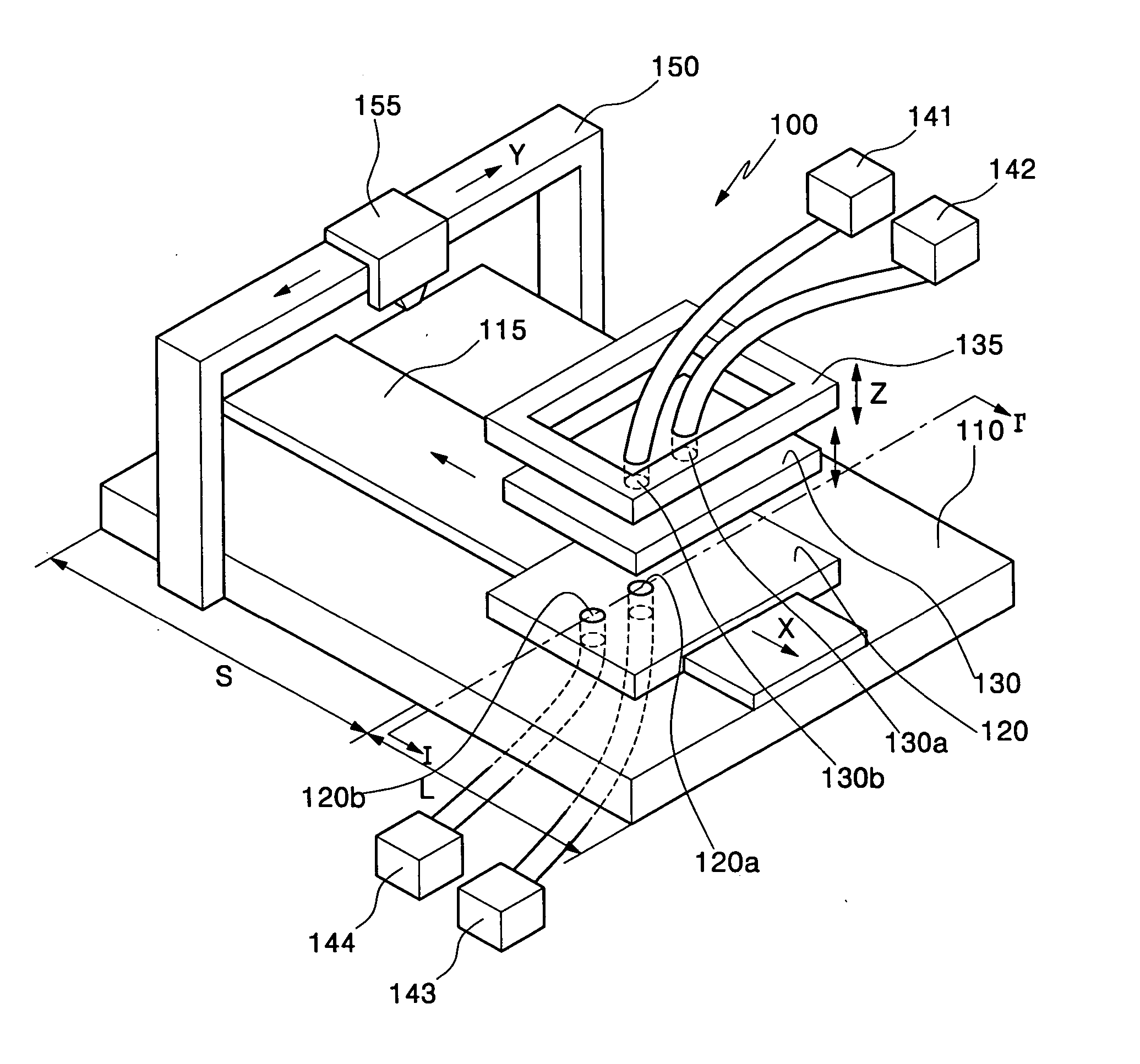
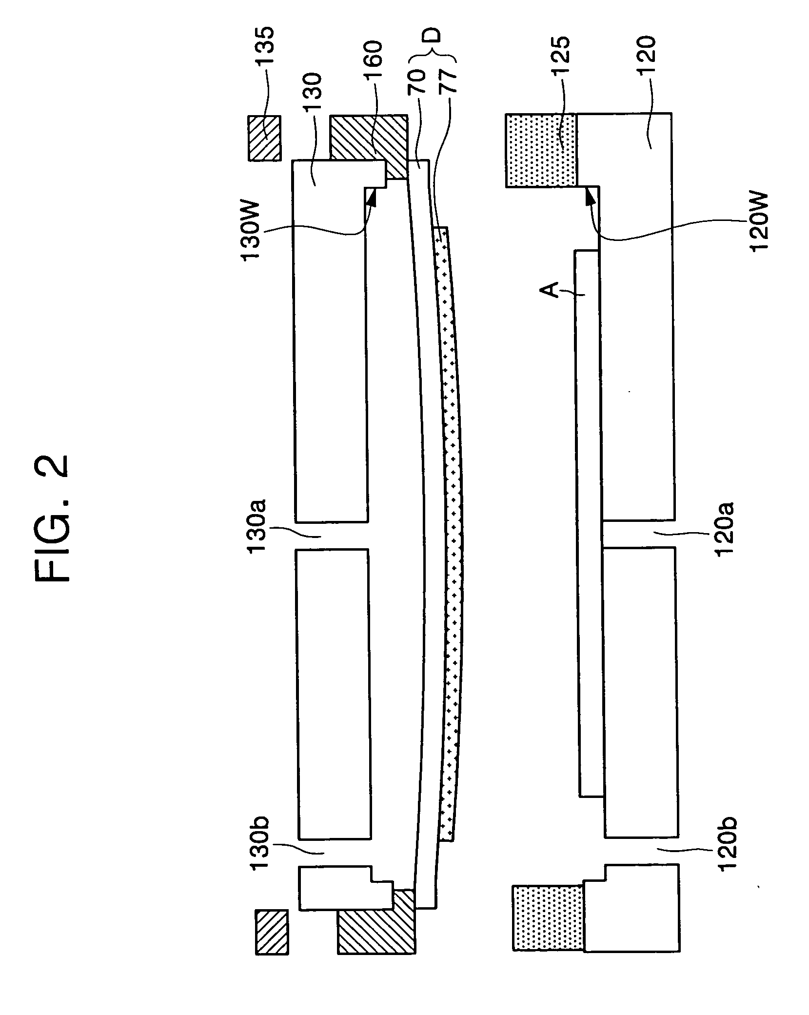
[0026]FIG. 1 is a perspective view of a Laser Induced Thermal Imaging (LITI) apparatus 100 according to an exemplary embodiment of the present invention, and FIG. 2 is a cross-sectional view taken along line I-I′ of FIG. 1.

[0027] Referring to FIGS. 1 and 2, the LITI apparatus 100 includes a stage 110 having a lamination region L and a laser irradiation region S. The stage 110 fixes ...


PUM

PropertyMeasurementUnit
Laser Induced Thermal Imagingaaaaaaaaaa
elasticaaaaaaaaaa
pressureaaaaaaaaaa

Abstract

Provided are a laser induced thermal imaging (LITI) apparatus, a laminator, and an LITI method using the apparatus. The LITI apparatus includes a chuck having at least one first lower ventilation hole for attracting a lower substrate toward the chuck. A cap is disposed on the chuck. The cap fixes an upper substrate and includes at least one first upper ventilation hole for pressurizing the upper substrate so that the upper substrate is closely adhered to the lower substrate. A laser irradiation system for irradiating a laser beam is disposed over the upper substrate adhered to the lower substrate. In this construction, the upper substrate can be laminated on the lower substrate.

Description

CLAIM OF PRIORITY [0001] This application makes reference to, incorporates the same herein, and claims all benefits accruing under 35 U.S.C. § 119 from an application for LASER INDUCED THERMAL IMAGING APPARATUS, LAMINATOR, AND LASER INDUCED THERMAL IMAGING METHOD USING THE APPARATUS earlier filed in the Korean Intellectual Property Office on the 20 of Oct., 2004 and there duly assigned Serial No. 2004-84150. BACKGROUND OF THE INVENTION [0002] 1. Field of the Invention [0003] The present invention relates to a Laser Induced Thermal Imaging (LITI) apparatus and, more particularly, to an LITI apparatus including a laminator and an LITI method using the apparatus. [0004] 2. Description of the Related Art [0005] In general, a Laser Induced Thermal Imaging (LITI) method requires at least a laser, an acceptor substrate, and a donor film. The donor film includes a base film, a Light-to-Heat Conversion (LTHC) layer, and a transfer layer. The donor film is laminated on the acceptor substrate ...

Claims


Application Information

Patent Timeline
Patent Type & Authority Applications(United States)
IPC IPC(8): B29C65/00B32B37/00
CPCB32B37/10B41J3/28B41J11/0085B41J11/06H01L51/0013H10K71/18H01L21/52H01L21/02
Inventor KANG, TAE-MINKIM, HYE-DONGSONG, MYUNG-WONLEE, JAE-HO
Owner SAMSUNG DISPLAY CO LTD
Why Eureka
Try Eureka