
Brightness adjustment method and image processing apparatus

a technology of image processing apparatus and brightness adjustment, which is applied in the direction of image enhancement, exposure control, color signal processing circuit, etc., can solve the problem of difficult to recognize fine detail structure in an image obtained by endoscopy compared with a photograph obtained, and achieve the effect of adjusting the brightness level of the imag

Inactive Publication Date: 2006-04-20
FUJIFILM CORP +1
View PDF5 Cites 29 Cited by
  • Summary
  • Abstract
  • Description
  • Claims
  • Application Information

AI Technical Summary

Benefits of technology

[0012] The third processing is a processing for adding an adjustment value of saturation, which is obtained by weighting the value of each pixel of the image based on the portion contributing to saturation, and an adjustment value of brightness, which is obtained by weighting the value of each pixel in the luminance distribution image, which corresponds to each pixel of the image, based on the portion contributing to brightness to the value of each pixel which forms the image. Since the adjustment value of saturation as well as the adjustment value of brightness is added to an original value, it is possible to adjust the brightness level of the image while considering the color of the image.
[0016] According to the present invention, the adjustment value of saturation as well as the adjustment value of brightness is added to the value of each pixel which forms the image. Therefore, it is possible to adjust the brightness level of the image while adjusting the contrast in color. If an allocation to the portion contributing to brightness and an allocation to the portion contributing to saturation are controlled, an image which has desired brightness, and which has desired color information can be reproduced.

Problems solved by technology

Therefore, it is difficult to recognize a fine-detail structure in an image obtained by endoscopy compared with a photograph obtained by a digital camera or the like.

Method used


Image

  • Brightness adjustment method and image processing apparatus
  • Brightness adjustment method and image processing apparatus
  • Brightness adjustment method and image processing apparatus

Examples


Embodiment Construction

[0038] As an embodiment of the present invention, an electronic endoscope system which is used for examination of digestive organs will be described below.

[0039] 1. System Configuration

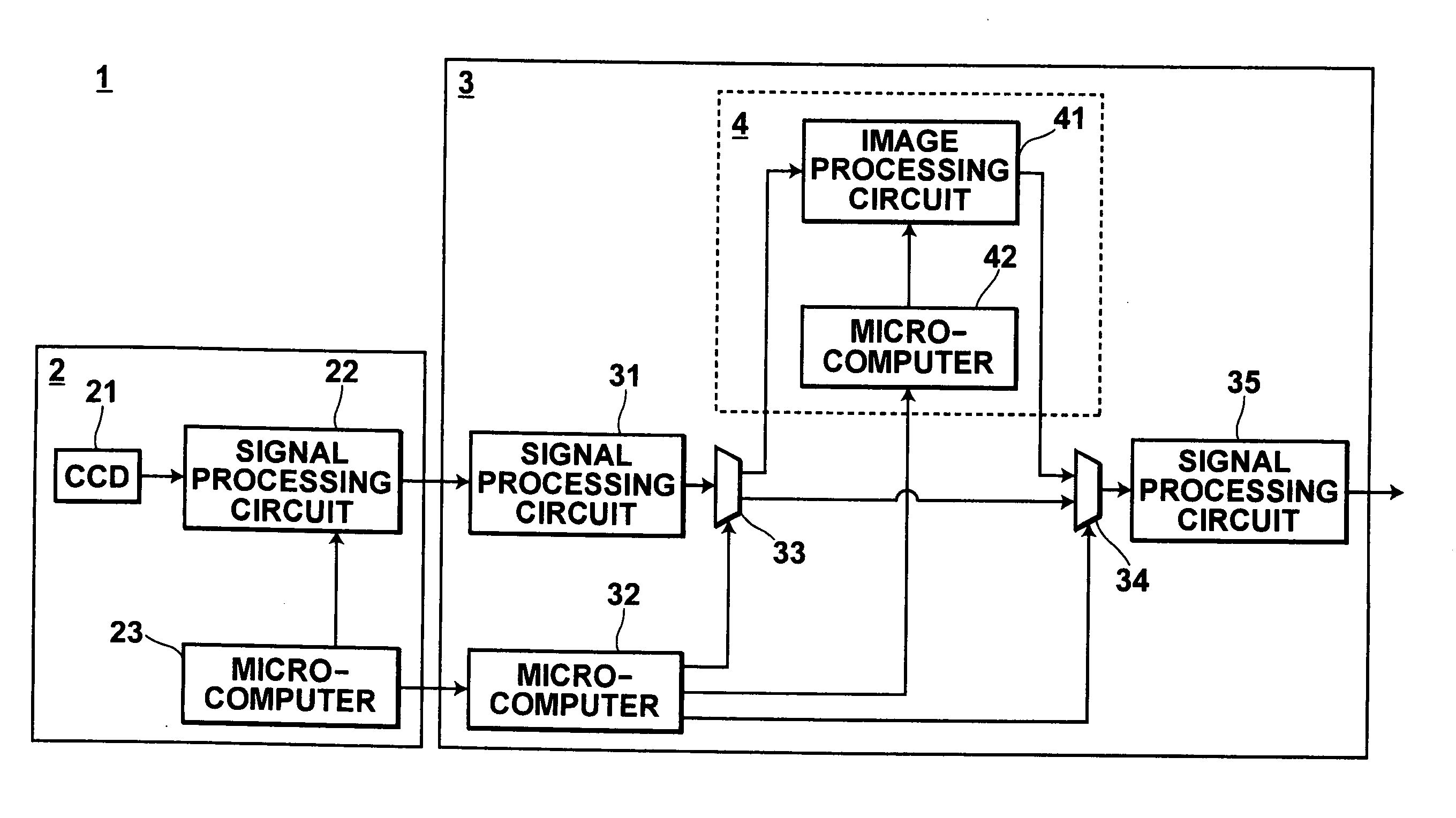
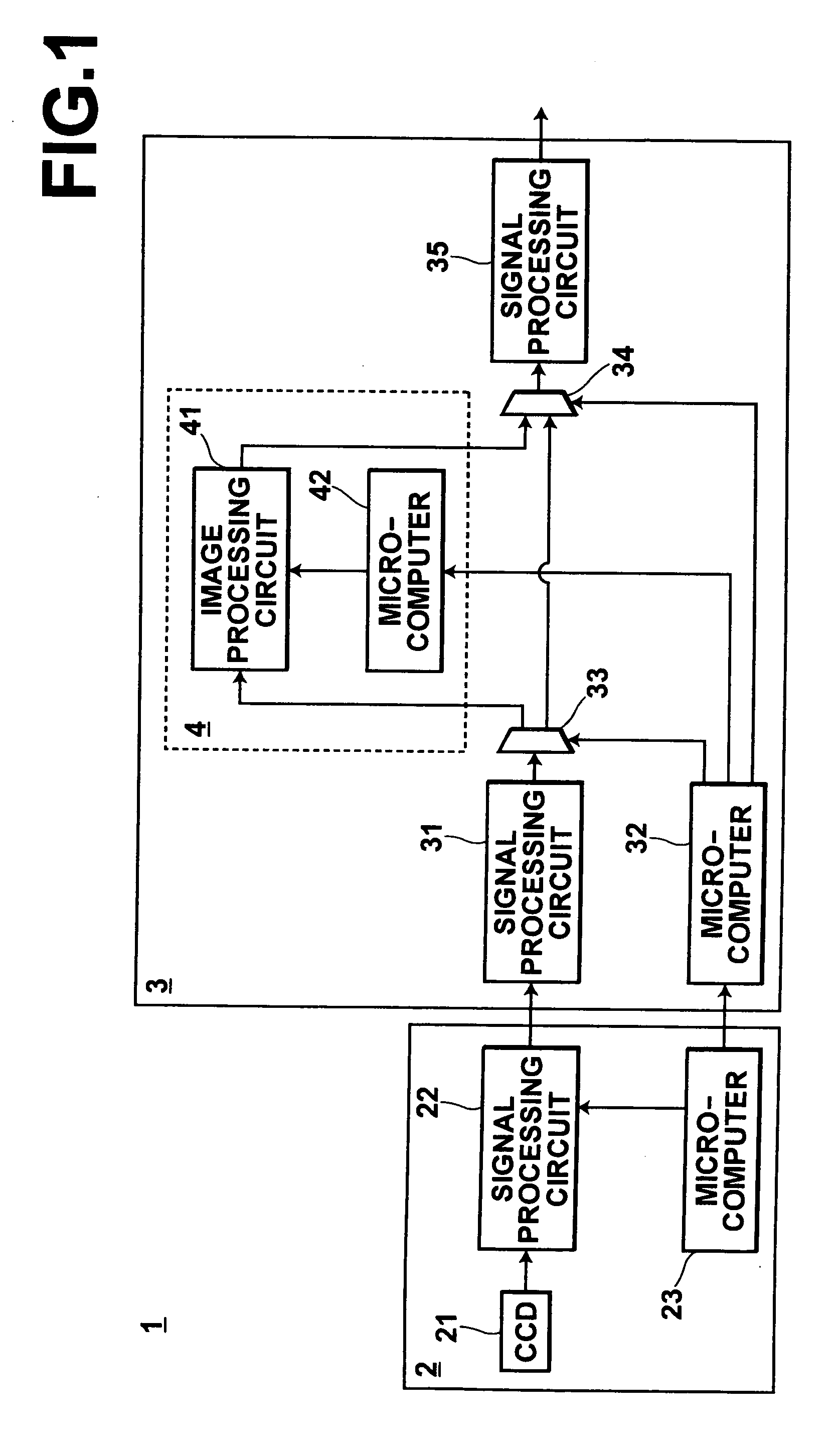
[0040]FIG. 1 is a schematic diagram illustrating the configuration of an electronic endoscope system. As illustrated in FIG. 1, the electronic endoscope system 1 includes an electronic endoscope 2 (hereinafter, referred to as a scope 2) and a processing apparatus (hereinafter, referred to as a video processor 3) which processes an image obtained by the electronic endoscope. The electronic endoscope system 1 also includes a light source device, monitor, printer, or the like, which are not illustrated. A plurality of kinds of scopes which are appropriate for the purpose of endoscopic examination may be used in the electronic endoscope system 1. In FIG. 1, elements which are common to all of the scopes are illustrated in the scope 2.

[0041] The scope 2 includes a CCD (Charge Coupled Device) 21 and a si...


PUM


Abstract

An adjustment amount of a brightness level is determined for each pixel of an image based on the value of each pixel of a luminance distribution image which represents the distribution of luminance of the image. A portion contributing to adjustment of brightness and a portion contributing to adjustment of saturation are determined for each pixel of the image so that the sum thereof is equal to the adjustment amount of the brightness level. Then, an adjustment value of saturation, which is obtained by weighting the value of each pixel in the image based on the portion contributing to saturation, and an adjustment value of brightness, which is obtained by weighting the value of each pixel in the luminance distribution image, which corresponds to each pixel of the image, based on the portion contributing to brightness are added to the value of each pixel of the image.

Description

BACKGROUND OF THE INVENTION [0001] 1. Field of the Invention [0002] The present invention relates to a method for adjusting the brightness level of an image and an image processing apparatus and an image processing program for adjusting the brightness level of the image based on the method. [0003] 2. Description of the Related Art [0004] Generally, the range of a brightness level which can be reproduced on photographic paper (photosensitive material) or on a monitor is narrower than that of a brightness level which can be obtained by an imaging element of a digital camera. Therefore, a function for adjusting the brightness level of the image is provided in an apparatus which reproduces a photographic image obtained by the digital camera on the photographic paper or the monitor. [0005] For example, an apparatus and a method for outputting a print of an image after compressing the dynamic range of the brightness level of the image is disclosed in U.S. Pat. No. 6,122,076. In this appar...

Claims


Application Information

Patent Timeline
IPC IPC(8): H04N5/235
CPCG06T5/008G06T2207/10068G06T2207/30004G06T5/94
Inventor DONOMAE, YOSHIFUMIABE, KAZUNORI
Owner FUJIFILM CORP
Learn More