Toy rifle backlash vibration structure
a backlash vibration and toy rifle technology, applied in the field of toy rifles, can solve the problems of small backlash vibration, inability to adjust, and inability to design, so as to facilitate the replacement of components and prolong the working life of the piston
- Summary
- Abstract
- Description
- Claims
- Application Information
AI Technical Summary
Benefits of technology
Problems solved by technology
Method used
Image
Examples
Embodiment Construction
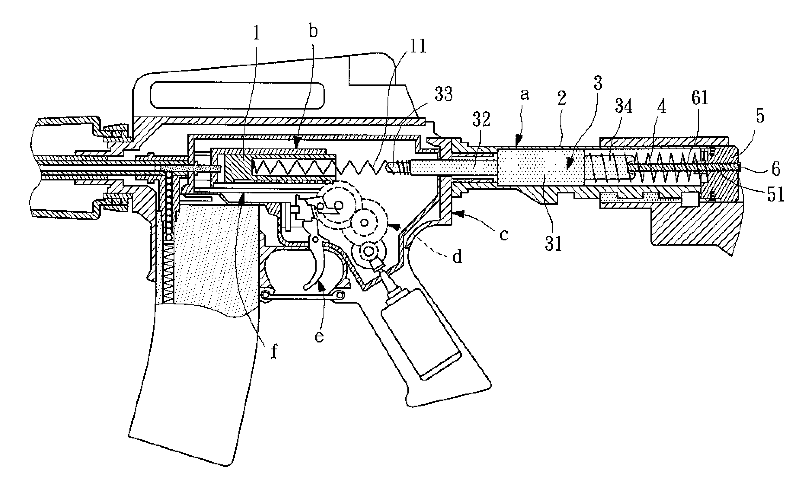
[0018]Referring to FIG. 3, a backlash vibration structure a is arranged at the rear side of a toy riffle in axial alignment with a piston 1 in a piston-cylinder mechanism b. The piston 1 has a piston spring 11 mounted in its rear side. The piston spring 11 has its one end received in the rear side of the piston 1. The toy riffle further comprises a transmission mechanism d, a trigger e and a bullet pusher f arranged under the piston-cylinder mechanism b. When pressed the trigger e, the transmission mechanism d is forced to move the piston-cylinder mechanism b, causing the bullet pusher f to push the bullet into the firing position for striking by (the firing pin of) the piston 1.
[0019]The backlash vibration structure a comprises a receiver extension 2, a weight 3, a reaction spring 4, and a buttcap spacer 5. The receiver extension 2 is connected to the rear side of the frame c of the toy riffle that accommodates the piston-cylinder mechanism b. The weight 3, the reaction spring 4 an...
PUM
 Abstract
Description
Claims
Application Information
 - R&D
- Intellectual Property
- Life Sciences
- Materials
- Tech Scout
- Unparalleled Data Quality
- Higher Quality Content
- 60% Fewer Hallucinations
Browse by: Latest US Patents, China's latest patents, Technical Efficacy Thesaurus, Application Domain, Technology Topic, Popular Technical Reports.
© 2025 PatSnap. All rights reserved.Legal|Privacy policy|Modern Slavery Act Transparency Statement|Sitemap|About US| Contact US: help@patsnap.com


