
A galvanically isolated resonant power converter assembly

Inactive Publication Date: 2018-06-21
NPC TECH APS
View PDF8 Cites 11 Cited by
  • Summary
  • Abstract
  • Description
  • Claims
  • Application Information

AI Technical Summary

Benefits of technology

The invention describes a power converter assembly with several advantages such as saving space and reducing costs. It uses semiconductor devices that communicate through magnetic coupling to synchronize their switching frequencies. This results in a maximized combined output voltage and minimized phase shift between the voltage and current waveforms. The phase shift can be adjusted to control the output voltage level. Overall, the assembly achieves higher efficiency and improved performance.

Problems solved by technology

Resonant power converters are particularly useful for high switching frequencies such as frequencies above 1 MHz where switching losses of standard SMPS topologies (Buck, Boost etc.) tend to be unacceptable for conversion efficiency reasons.
However, it remains a significant challenge to find suitable semiconductor switching devices which can operate at high switching frequencies, such as above 1 MHz or above 30 MHz within the VHF range, and handle necessary device voltages and currents to produce a required output power of the resonant power converter for numerous types of applications.
Unfortunately, isolation capacitors capable of complying with such official safety ratings are physically larger and more expensive than ordinary capacitors of similar capacitance without an official safety rating.
Hence, the traditional application of safety rated isolation capacitors as capacitive isolation barriers for each individual resonant power inverter increases the dimensions and costs of the galvanically isolated power converter assembly in an undesir-able manner.

Method used


Image

  • A galvanically isolated resonant power converter assembly
  • A galvanically isolated resonant power converter assembly
  • A galvanically isolated resonant power converter assembly

Examples


first embodiment

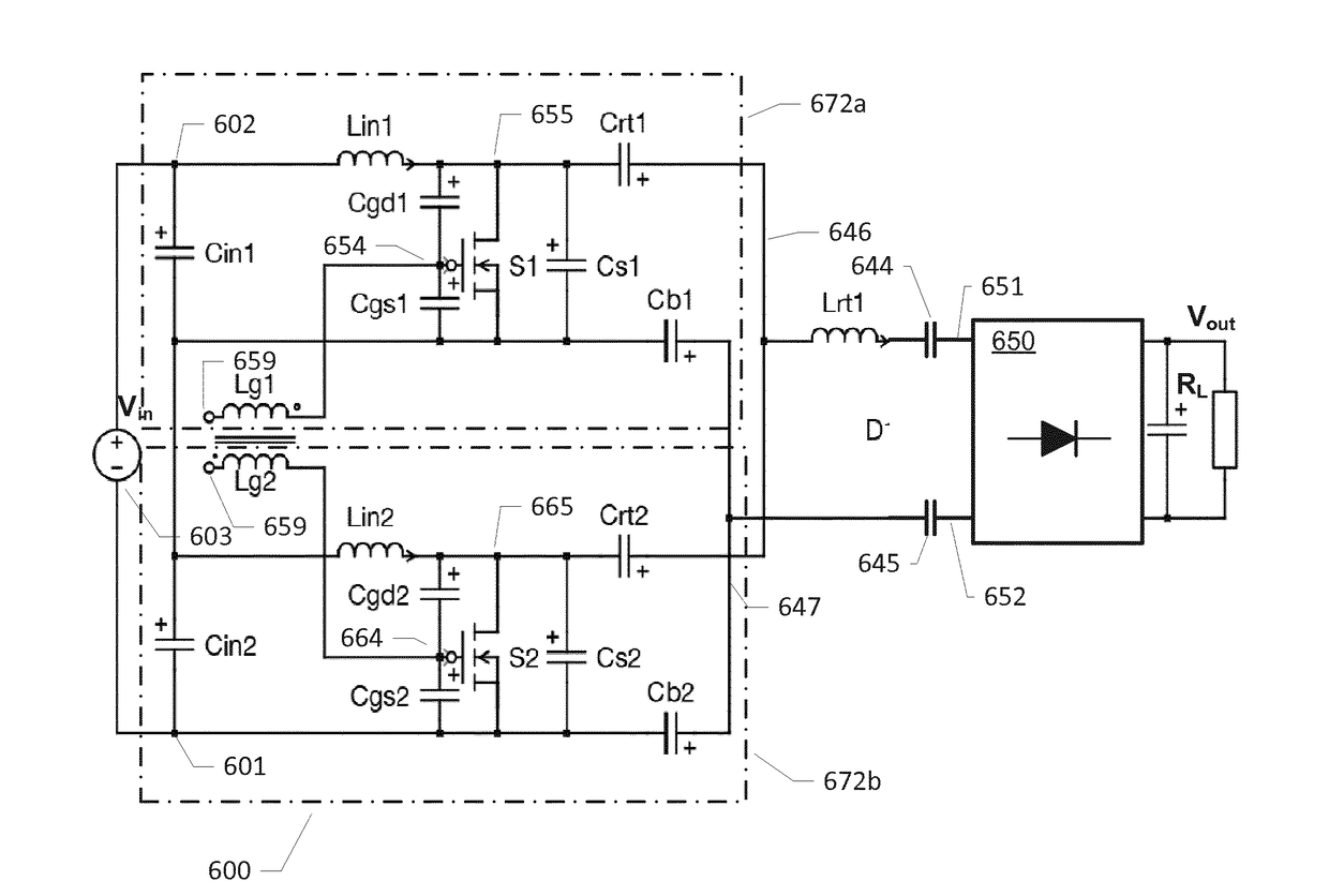
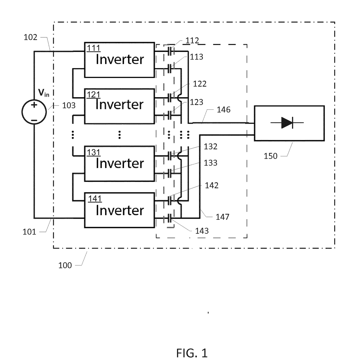
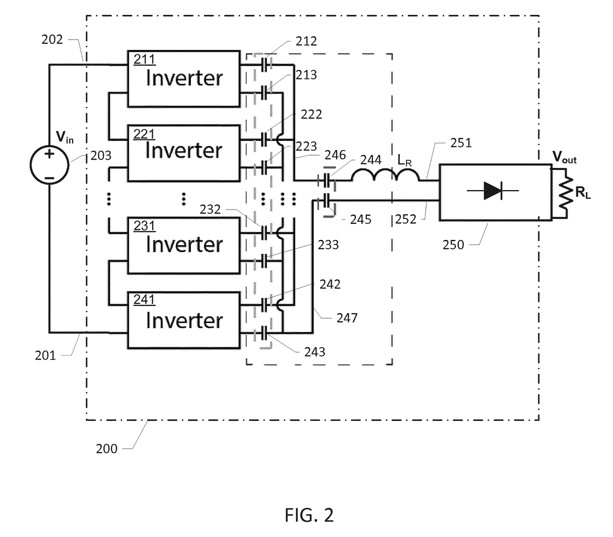
[0040]FIG. 2 shows a schematic block diagram of a galvanically isolated DC-DC power converter assembly 200 comprising a plurality of electrically interconnected individual resonant power inverters 211, 221, 231, 241 in accordance with the invention. Inputs of the plurality of electrically interconnected individual resonant power inverters 211, 221, 231, 241 are serially connected to a dc or ac voltage or power source 203. The skilled person will understand that alternative embodiments of the galvanically isolated DC-DC power converter assembly 200 may comprise less than four individual resonant power inverters, for example two or three resonant power inverters, while other embodiments may comprise more than four individual resonant power inverters, for example five or more individual resonant power inverters. The plurality of interconnected individual resonant power inverters 211, 221, 231, 241 may possess identical circuit topologies. Different types of resonant power inverters 211...

second embodiment

[0048]FIG. 2A shows a schematic block diagram of a galvanically isolated DC-DC power converter assembly 200a comprising a plurality of serially interconnected individual resonant power inverters 211, 221, 231, 241 in accordance with the invention. Inputs of the plurality of electrically interconnected individual resonant power inverters 211, 221, 231, 241 are serially connected to a dc or ac voltage or power source 203 via a positive input terminal 202a and a negative input terminal 201a of the assembly 200a. The skilled person will appreciate that the ordinary converter capacitor 212 of the previous converter embodiment connected in series with the positive output of the first resonant power inverter 211 has been replaced by a short circuit. Likewise, the ordinary converter capacitor 213 of the previous converter embodiment connected in series with the negative output of the fourth first resonant power inverter 241 has been left out and replaced by a short circuit.

[0049]This embodi...

third embodiment

[0055]FIG. 4 shows a simplified schematic block diagram of a galvanically isolated DC-DC power converter assembly 400 comprising a first set of electrically interconnected individual load circuits 450a, 450b, 450c and 450d in accordance with the invention. The skilled person will understand that alternative embodiments of the galvanically isolated DC-DC power converter assembly 400 may comprise fewer than four individual load circuits, for example two or three individual load circuits, while other alternative embodiments may comprise more than four individual load circuits. The plurality of interconnected individual load circuits 450a, 450b, 450c and 450d may possess identical circuit topologies. The galvanically isolated DC-DC power converter assembly 400 further comprises a common resonant power inverter 411, which is electrically coupled to the first set of electrically interconnected individual load circuits 450a, 450b, 450c and 450d via a capacitive galvanic isolation barrier a...


PUM


Abstract

The present invention relates in a first aspect to a galvanically isolated power converter assembly comprising a first set of electrically interconnected resonant power inverters configured for generating respective output voltages and output currents. The galvanically isolated power converter assembly further a first positive summing node and a first negative summing node configured to combining the output voltages and output currents of the first set of resonant power inverters and a first common load circuit comprising a positive load input and a negative load input. A galvanic isolation barrier comprises first and second common isolation capacitors electrically insulating the common load circuit. Each of the first and second common isolation capacitors possesses an official safety rating.

Description

[0001]The present invention relates in a first aspect to a galvanically isolated power converter assembly comprising a first set of electrically interconnected resonant power inverters configured for generating respective output voltages and output currents. The galvanically isolated power converter assembly further a first positive summing node and a first negative summing node configured to combining the output voltages and output currents of the first set of resonant power inverters and a first common load circuit comprising a positive load input and a negative load input. A galvanic isolation barrier comprises first and second common isolation capacitors electrically insulating the common load circuit. Each of the first and second common isolation capacitors possesses an official safety rating.BACKGROUND OF THE INVENTION[0002]Power density and component costs are key performance metrics of both isolated and non-isolated resonant DC-DC power converters to provide the smallest pos...

Claims


Application Information

Patent Timeline
IPC IPC(8): H02M7/493H02M3/335H02M7/537
CPCH02M7/493H02M3/33569H02M7/537H02M2007/4815H02M2001/0058H02M1/083H02M3/155H02M3/1584H02M3/338H02M7/5383Y02B70/10H02M1/0074H02M1/0077H02M1/0058H02M3/1557H02M7/4815H02M7/05H02M3/01
Inventor ANDERSEN, THOMASMONSTER, JAKOB DOLLNER
Owner NPC TECH APS
Learn More