Method of producing optical element by patterning liquid crystal films

a liquid crystal film and patterning technology, applied in the direction of polarising elements, instruments, chemistry apparatus and processes, etc., can solve the problems of low patterning precision, inability to form colored patterns by removing a part of cholesteric liquid crystal film, and inability to maintain film thickness precision high, high precision and efficiency, the effect of high precision

Inactive Publication Date: 2006-04-20
DAI NIPPON PRINTING CO LTD
View PDF3 Cites 2 Cited by
  • Summary
  • Abstract
  • Description
  • Claims
  • Application Information

AI Technical Summary

Benefits of technology

[0011] The present invention was accomplished in the light of the aforementioned drawbacks in the related art. An object of the present invention is therefore to provide a method of producing an optical element having excellent optical properties by patterning liquid crystal films in the same or different patterns on a substrate with high precision and efficiency.
[0017] In the above-described second aspect of the present invention, it is preferable that, in the fourth step, the second radiation-curing liquid crystal is applied to a surface of the first liquid crystal film, which remains on the substrate after removing the uncured portion of the first liquid crystal film, as well as the exposed surface of the substrate; and, in the second step, the radiation-applied-portion of the first liquid crystal film is cured to such an extent that 90% or more of the first radiation-curing liquid crystal is cured, so as to keep the aligning function of the surface of the first liquid crystal film, to which the second radiation-curing liquid crystal is applied in the fourth step.
[0022] According to the present invention, a liquid crystal film in the desired pattern is obtained by selectively applying radiation to the desired portion of a liquid crystal film formed on a substrate having the aligning function, so as to partially cure the liquid crystal film, and then bringing the partially cured liquid crystal film into contact with an organic solvent to remove the uncured portion of the liquid crystal film. It is, therefore, possible to pattern the liquid crystal film as desired with high accuracy and efficiency while maintaining film-thickness precision high.
[0023] In particular, according to the present invention, in the aforementioned step of selectively applying radiation to the desired portion of the liquid crystal film to partially cure it, the radiation-applied-portion of the first liquid crystal film may be cured to such an extent that 90% or more of the first radiation-curing liquid crystal is cured. In this case, even when a liquid crystal is applied again to the surface of the liquid crystal film, liquid crystalline molecules in this liquid crystal are properly aligned. It is thus possible to form, on one substrate, a plurality of liquid crystal films in such patterns that they are overlapped each other, with high precision and efficiency.
[0024] Also, according to the present invention, in the aforementioned step of bringing the partially cured liquid crystal film into contact with an organic solvent to remove the uncured portion of it, as the organic solvent, an organic solvent that does not dissolve the surface of a substrate having the aligning function may be used. In this case, even when a liquid crystal is applied again to the surface of the substrate, liquid crystalline molecules in this liquid crystal are properly aligned. It is thus possible to form, on one substrate, a plurality of liquid crystal films in different patterns, with high precision and efficiency.

Problems solved by technology

The above-described method (1) utilizes temperature changes to control colors, so that this method has such problems that patterning precision is low and that the patterned cholesteric liquid crystal films of different colors show extremely poor optical properties at the boundaries between them.
Moreover, although it is possible, by this method, to form red-, green- and blue-colored patterns on one cholesteric liquid crystal film, it is impossible to form the colored patterns by removing a part of a cholesteric liquid crystal film.
The method (1) is thus disadvantageous in that a cholesteric liquid crystal film cannot be patterned into a shape whose outline coincides with the external shape of an optical element.
Problems with this method are, therefore, such that colored patterns cannot be obtained with high positional precision and thickness precision and that many hours are required for production.
The above-described method (3) requires complicated production processes.
Moreover, the patterned cholesteric liquid crystal films obtained by this method are poor in optical properties, heat resistance, chemical resistance, etc.
One problem with this technique is that high thickness precision cannot be attained at the boundaries between patterns of different colors.
In addition, the surface of the substrate having the function of aligning liquid crystalline molecules tends to be damaged, so that when a liquid crystal is applied again to this surface, liquid crystalline molecules in this liquid crystal are not easily aligned.
However, this method is merely meant for forming a single liquid crystal film on a substrate; and there is no consideration for how the organic solvent affects the aligning function of the substrate or the liquid crystal film.

Method used


Image

  • Method of producing optical element by patterning liquid crystal films
  • Method of producing optical element by patterning liquid crystal films
  • Method of producing optical element by patterning liquid crystal films

Examples


example 1

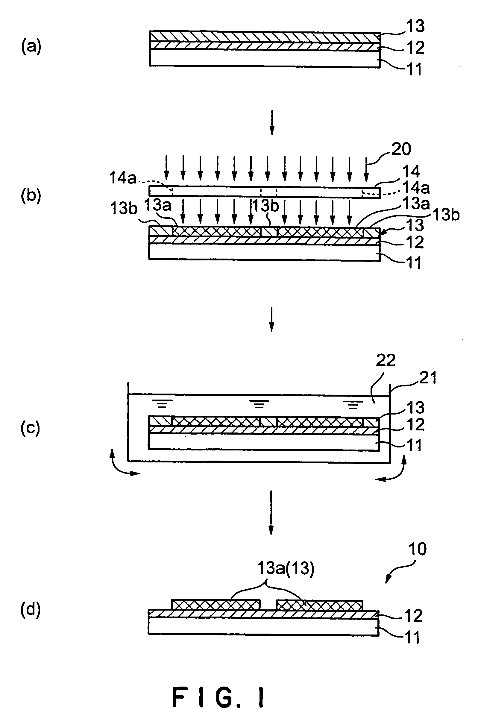
[0052] In toluene were dissolved: 89 parts of a monomer containing, in its molecules, polymerizable acrylates at both ends and spacers between mesogen existing at the center and the acrylates, having a liquid crystalline phase transition temperature of 100° C.; and 11 parts of a chiral agent having, in its molecule, polymerizable acrylates at both ends. To this toluene solution was added a photopolymerization initiator (“Irg 184” available from Ciba Specialty Chemicals K.K., Japan) in an amount of 5% by weight of the above-described monomer.

[0053] Separately, polyimide was applied to a glass substrate; and the polyimide film formed was rubbed in a definite direction to make it into an alignment layer.

[0054] The glass substrate provided with this alignment layer was set in a spin coater; and the alignment layer was spin-coated with the above-prepared toluene solution so that the thickness of the toluene solution applied would be approximately 10 μm.

[0055] The glass substrate coate...

example 2

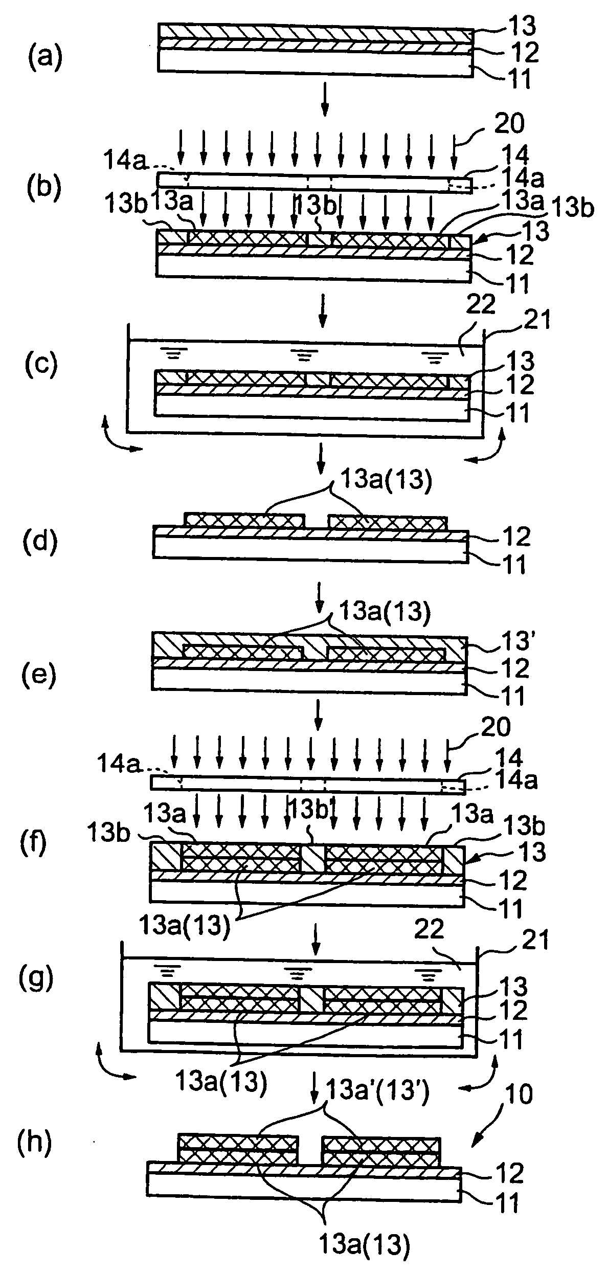
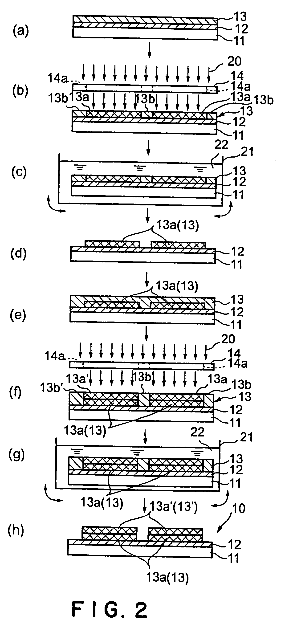
[0060] On the glass substrate provided with the alignment layer having thereon the cholesteric liquid crystal film patterned as desired, produced in Example 1, an additional cholesteric liquid crystal film was formed and patterned in the same manner as in Example 1.

[0061] The pattern of this newly formed additional cholesteric liquid crystal film was different from that of the cholesteric liquid crystal film formed in Example 1. Namely, a part of the patterned additional cholesteric liquid crystal film was present on the surface of the patterned cholesteric liquid crystal film formed in Example 1, and the rest of the patterned additional cholesteric liquid crystal film was present on the exposed surface of the alignment layer.

[0062] It was confirmed that the additional cholesteric liquid crystal film formed in this example was nearly uniform in thickness (3 μm) and that the pattern formed was extremely precise. In addition, although the patterned additional cholesteric liquid crys...

example 3

[0063] In the composition of the toluene solution used in Example 1, the amount of the chiral agent was changed to prepare three liquid crystals having selective reflection wavelengths of red, green and blue.

[0064] The same steps of forming and patterning a cholesteric liquid crystal film as those in Example 2 were repeated for each of these three cholesteric liquid crystals, provided that the patterning was conducted so that the resulting three cholesteric liquid crystal films would not be superposed on each other. Thus, a color filter having red-, green- and blue-colored patterns was obtained.

[0065] It was confirmed that the patterned cholesteric liquid crystal films of red, green and blue formed in this example, constituting the color filter, were nearly uniform in thickness (3 μm) and that the patterns formed were extremely precise. In addition, all of these additional cholesteric liquid crystal films of red, green and blue were found to be excellent in the state of alignment ...


PUM

PropertyMeasurementUnit
liquid crystalline phase transition temperatureaaaaaaaaaa
thicknessaaaaaaaaaa
degree of polymerizationaaaaaaaaaa

Abstract

A radiation-curing liquid crystal having cholesteric regularity is applied to a glass substrate 11 provided with an alignment layer 12 to form a first cholesteric liquid crystal film 13 in the uncured state (FIG. 2(a)). Radiation 20 is then selectively applied, through a photomask 14, to the desired portions of the first cholesteric liquid crystal film 13 to partially cure it (FIG. 2(b)); thereafter, the first cholesteric liquid crystal film 13 is immersed in an organic solvent 22 to remove the uncured portions 13b thereof (FIG. 2(c)), thereby forming the first cholesteric liquid crystal film 13 in a desired pattern (FIG. 2(d)). Then, in the same manner as described above, a radiation-curing liquid crystal having cholesteric regularity is applied to the surface of the formed first cholesteric liquid crystal film 13 and the alignment layer 12 to form a second cholesteric liquid crystal film 13′ in the uncured state (FIG. 2(e)). To the second cholesteric liquid crystal film 13′, application of radiation 20 (FIG. 2(f)) and immersion in an organic solvent 22 (FIG. 2(g)) are carried out to remove the uncured portions 13b′ thereof (FIG. 2(e)), thereby producing an optical element 10 having the cholesteric liquid crystal films 13 and 13′ in desired patterns (FIG. 2(h)).

Description

BACKGROUND OF THE INVENTION [0001] 1. Field of the Invention [0002] The present invention relates to a process for producing an optical element such as a circularly-polarized-light-separating element or a color filter, and particularly to a method of producing an optical element by patterning liquid crystal films. [0003] 2. Description of Related Art [0004] There has conventionally been known a process for producing an optical element such as a circularly-polarized-light-separating element or a color filter by the use of liquid crystal films having cholesteric regularity (cholesteric films). In such a process for producing an optical element, it is necessary to form a pattern whose outline coincides with the external shape of the optical element, or to form red-, green- and blue-colored patterns. There is, therefore, a demand for a method of patterning cholesteric liquid crystal films with high precision and efficiency. [0005] Conventionally known methods of forming red-, green- and...

Claims


Application Information

Patent Timeline
Patent Type & Authority Applications(United States)
IPC IPC(8): G02F1/13G02F1/1335G02B5/30
CPCG02B5/3016G02F1/1335
Inventor UMEYA, MASANORI
Owner DAI NIPPON PRINTING CO LTD
Why Eureka
Try Eureka