Optical amplifying apparatus, optical transmission system and method of adjusting optical transmission loss

a technology of optical amplifier and optical transmission system, which is applied in the direction of electromagnetic transmission, transmission monitoring, electromagnetic repeaters, etc., can solve the problems of inability to adjust the input level of the optical amplifier or the input level of the optical amplifier, and the level of the signal light inputted to the optical amplifier is never maintained constant,

Active Publication Date: 2006-04-20
NEC CORP
View PDF10 Cites 10 Cited by
  • Summary
  • Abstract
  • Description
  • Claims
  • Application Information

AI Technical Summary

Benefits of technology

[0009] In consideration of the above problems, it is an exemplary object of the present invention to provide an optical amplifier and an optical transmission system, which enable an optical transmission loss to be easily adjusted, and to provide a method of adjusting the loss easily.

Problems solved by technology

However, there are a wide variety of transmission distances and optical transmission lines between optical amplifying repeaters, and there are various optical transmission losses.
Thus, the level of the signal light inputted to the optical amplifier is never maintained constant.
Thus, there is a problem that the input level of the optical amplifier or the optical transmission loss cannot be adjusted unless equipment and preparations for transmitting the signal light are completed.

Method used


Image

  • Optical amplifying apparatus, optical transmission system and method of adjusting optical transmission loss
  • Optical amplifying apparatus, optical transmission system and method of adjusting optical transmission loss
  • Optical amplifying apparatus, optical transmission system and method of adjusting optical transmission loss

Examples


Embodiment Construction

[0026] With reference to the drawings, exemplary embodiments of the present invention will be described in detail below. Note that the exemplary embodiments described below show concrete examples for understanding the present invention, and the scope of the present invention is not limited only to those embodiments.

[0027] Note that an optical amplifying apparatus, an optical detecting unit, an optical amplifying unit, an optical attenuating unit and an optical blanching unit in the scope of claims will be specifically translated into an optical amplifying repeater, a photoelectric converter, an optical amplifier, an optical attenuator and an optical coupler, respectively. These are one example of the present invention, and the scope of claims of the present invention is not limited thereto.

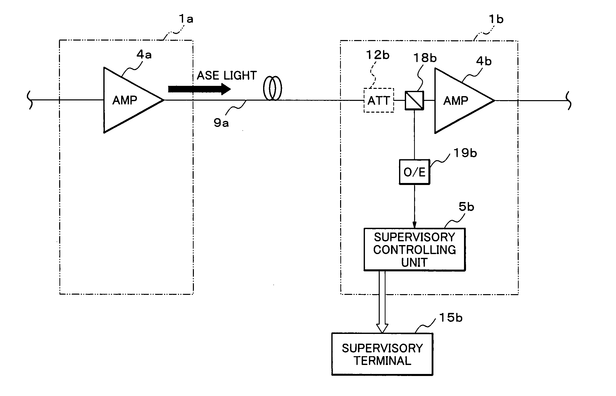
[0028]FIG. 1 is a schematic diagram showing an optical transmission system according to a first exemplary embodiment of the present invention. FIGS. 2A and 2B are explanatory views showing input...


PUM


Abstract

An optical amplifying apparatus connected mutually through an optical transmission line includes an optical detecting unit for detecting an input level of an amplified spontaneous emission (ASE) light, an optical amplifying unit for amplifying a signal light, and an optical attenuating unit for adjusting an attenuation level for the signal light, which being installed on an input side of the optical amplifying unit. The optical attenuating unit adjusts the attenuation level for the signal light, based on a difference between an output level of the ASE light outputted from the preceding optical amplifying apparatus and the input level of the ASE light inputted thereto.

Description

BACKGROUND OF THE INVENTION [0001] 1. Field of the Invention [0002] The present invention relates to an optical amplifying apparatus connected mutually through an optical transmission line, an optical transmission system and a method of adjusting an optical transmission loss thereof. [0003] 2. Description of the Related Art [0004] Development of a long-distance optical transmission system has been advancing in recent years. The long-distance optical transmission system is realized by connecting a number of optical amplifying repeaters to a sequence in an optical transmission line. FIG. 9 shows one example of a wavelength division multiplexing optical transmission system related to the present invention. Line terminating equipments (LTEs) 501 and 502 are connected to each other through optical transmission lines 530 to 53n. In the optical transmission lines 530 to 53n, n of optical amplifying repeaters 511 to 51n is provided in multiple stages. The wavelength division multiplexing op...

Claims


Application Information

Patent Timeline
IPC IPC(8): H01S3/00H04B10/07H04B10/077H04B10/29H04B10/294
CPCH01S3/10H01S3/10015H04B10/2931
InventorYAMASHITA, MAKOTO
OwnerNEC CORP