Beacon signals facilitating signal detection and timing synchronization

a technology of beacon signals and beam signals, applied in the direction of synchronising signal speed/phase control, multiplex communication, transmission monitoring, etc., to facilitate the use of energy detection techniques

Inactive Publication Date: 2006-04-20
QUALCOMM INC
View PDF6 Cites 20 Cited by
  • Summary
  • Abstract
  • Description
  • Claims
  • Application Information

AI Technical Summary

Benefits of technology

[0023] The beacon signal of the present invention having a duration of multiple symbol transmission times facilitates the use of energy detection techniques since the energy of the signal will be present for more than a single symbol transmission time period. Thus, a receiver which is not perfectly synchronized with the transmitter should be able to measure received signal energy for a period of time in which a beacon signal is received, e.g., a symbol transmission time period, without having to be perfectly synchronized with the transmitter of the beacon signal.

Problems solved by technology

However, this is not mandatory and may not occur in some implementations.

Method used


Image

  • Beacon signals facilitating signal detection and timing synchronization
  • Beacon signals facilitating signal detection and timing synchronization
  • Beacon signals facilitating signal detection and timing synchronization

Examples


Embodiment Construction

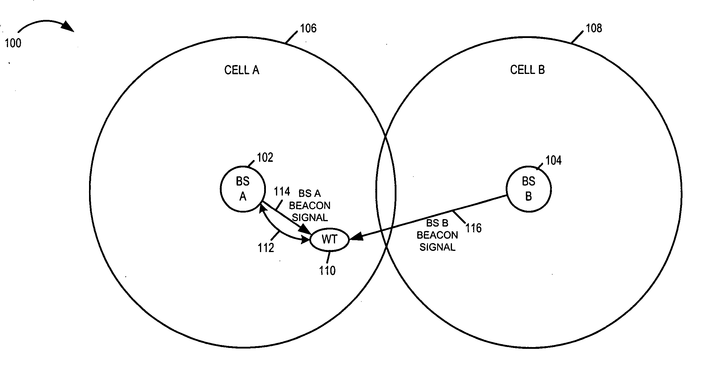
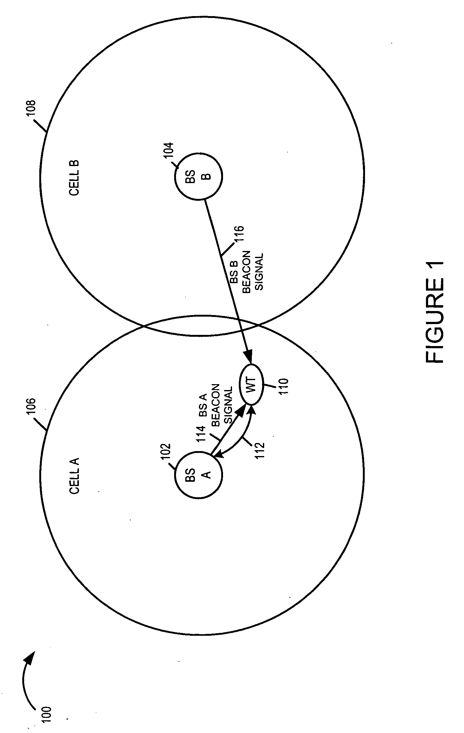
[0025]FIG. 1 is a drawing of an exemplary wireless communications system 100 implemented in accordance with the present invention, the exemplary system 100 including two adjacent base stations, base station A (BS A) 102 and base station B (BS B) 104. Cell A 106 represents the wireless coverage area of BS A 102, while cell B 108 represents the wireless coverage area of BS B 104. Wireless terminals (WTs), e.g., mobile nodes, may move through the cells of the system, and may communicate with peer nodes, e.g., other WTs through the base stations. Exemplary WT 110, implemented in accordance with the present invention, shown in FIG. 1 is currently using BS A 102 as its point of network attachment and communicates with BS A 102 through wireless communication link 112. Each base station, (BS A 102, BS B 104), transmits, e.g., periodically, a beacon signal, e.g., a relatively short duration high power OFDM signal with the base station transmission power concentrated primarily on one or a few...


PUM


Abstract

Improved beacon signaling methods are described. Beacon signals are transmitted on the same tone in at least two consecutive symbol periods facilitating accurate energy measurements over a symbol period even if timing synchronization with the transmitter is not maintained. A low power wideband signal is also combined with the beacon signal to facilitate channel estimation and other operations such as timing synchronization operations.

Description

RELATED APPLICATIONS [0001] The present application claims the benefit of U.S. Provisional Patent Application S.N. 60 / 618,720, filed on Oct. 14, 2004, titled “IMPROVED BEACON SIGNALS FACILITATING SIGNAL DETECTION AND TIMING SYNCHRONIZATION”, which is hereby expressly incorporated by reference.FIELD OF THE INVENTION [0002] The present invention relates to methods and apparatus for providing signals suitable for identifying transmitter and / or making timing or other adjustments relative to a transmitter and, more particularly, to methods and apparatus for generating and using improved beacon signals. BACKGROUND [0003] Narrow high powered signals may be transmitted periodically from a base station transmitter to allow a mobile device to identify a nearby transmitter and make various signal measurements. The signal measurements may be used to determine the relative strength of signals received from different transmitters and / or to make mobile adjustments, e.g., timing adjustments to faci...

Claims


Application Information

Patent Timeline
Patent Type & Authority Applications(United States)
IPC IPC(8): H04J3/06
CPCH04B1/40H04L7/08H04L27/2655H04L27/2613
Inventor LAROIA, RAJIVPARIZHSKY, VLADIMIRLI, JUNYIUPPALA, SATHYADEV VENKATA
Owner QUALCOMM INC
Why Eureka
Try Eureka