Method and System for Scatter Correction During Bi-Plane Imaging with Simultaneous Exposure

a scatter correction and simultaneous exposure technology, applied in the field of x-ray systems, can solve the problems of reducing the imaging rate, reducing the detection primary image, and not supporting a mechanism equivalent to the “blanking” capability of the image intensifier, so as to achieve equal imaging rates, improve the imaging rate of the alternate bi-plane method, and improve the effect of image quality

Inactive Publication Date: 2006-04-20
GE MEDICAL SYST GLOBAL TECH CO LLC
View PDF13 Cites 21 Cited by
  • Summary
  • Abstract
  • Description
  • Claims
  • Application Information

AI Technical Summary

Benefits of technology

[0014] One advantage of the present invention is that it includes a method to achieve equivalent imaging rates during simultaneous bi-plane operation which are substantially similar to those achieved during single plane operation without the need of performance improvements within the x-ray source or x-ray detector to increase the imaging rates of the alternate bi-plane method. This enables the direct application of digital detector technology into bi-plane applications.
[0015] Additionally, the invention promotes the use of simultaneous bi-plane, which is highly desirable. Alternate bi-plane has prevailed, as a result of superior image quality through the avoidance of the effects of scatter, but it can not provide simultaneous views of the object under study, which is the objective of bi-plane imaging. Only simultaneous bi-plane achieves this objective.

Problems solved by technology

For many relative projection angles, the amount of scatter radiation is significant and renders the detected primary image unacceptable for diagnosis.
One disadvantage of digital x-ray detection technology is it does not support a mechanism equivalent to the “blanking” capability of the image intensifier.
Because of this, as digital x-ray detectors are introduced into bi-plane applications, the aforementioned alternate bi-plane method must be utilized, but the reduction in imaging rate makes this an inefficient solution.
The disadvantages associated with current, scanning systems have made it apparent that a new technique for scanning and data transfer is needed.

Method used


Image

  • Method and System for Scatter Correction During Bi-Plane Imaging with Simultaneous Exposure
  • Method and System for Scatter Correction During Bi-Plane Imaging with Simultaneous Exposure
  • Method and System for Scatter Correction During Bi-Plane Imaging with Simultaneous Exposure

Examples


Embodiment Construction

[0023] The present invention is illustrated with respect to a diagnostic x-ray imaging system 10 particularly suited to the medical field. The present invention is, however, applicable to various other uses that may require scanning, as will be understood by one skilled in the art, e.g. baggage scanners, vehicle scanners, moving object scanners, liquid scanners, etc.

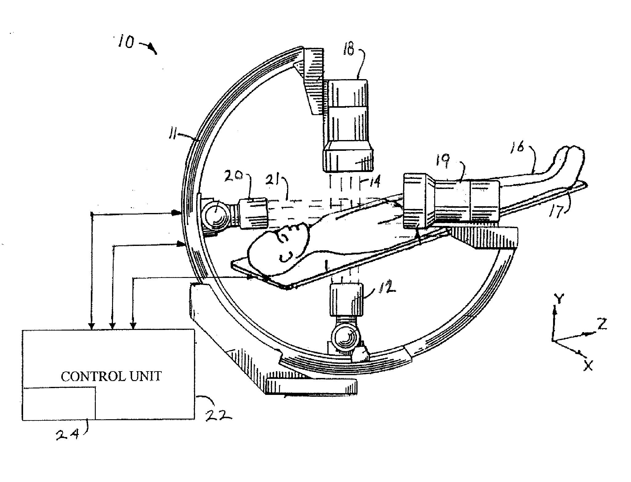
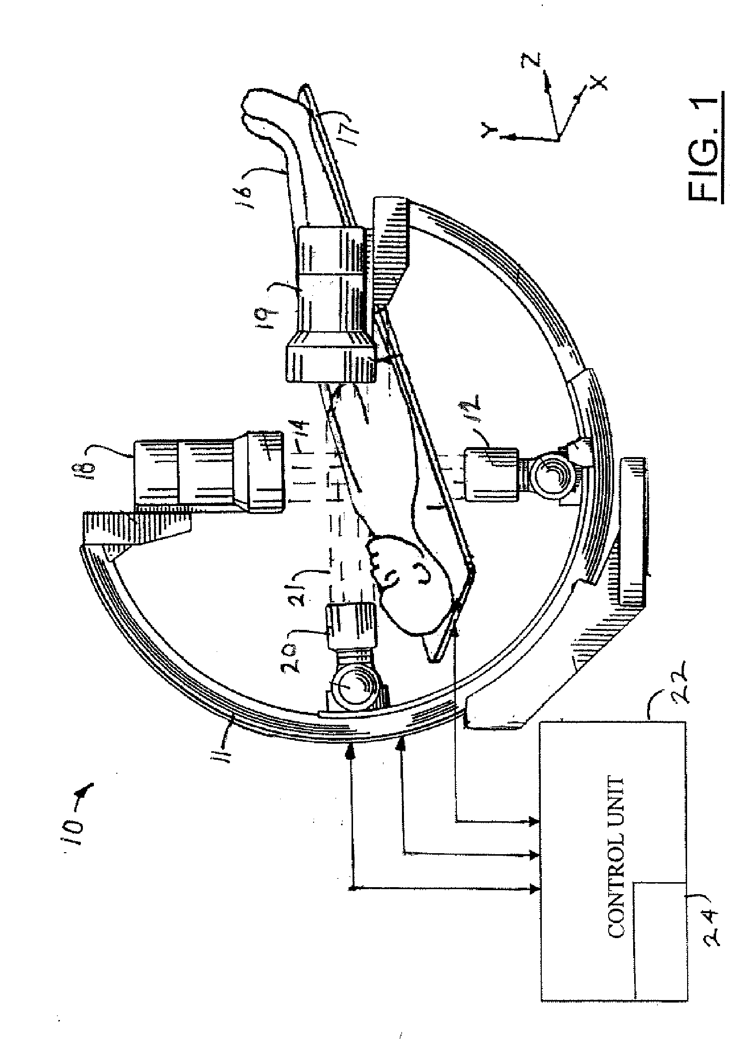
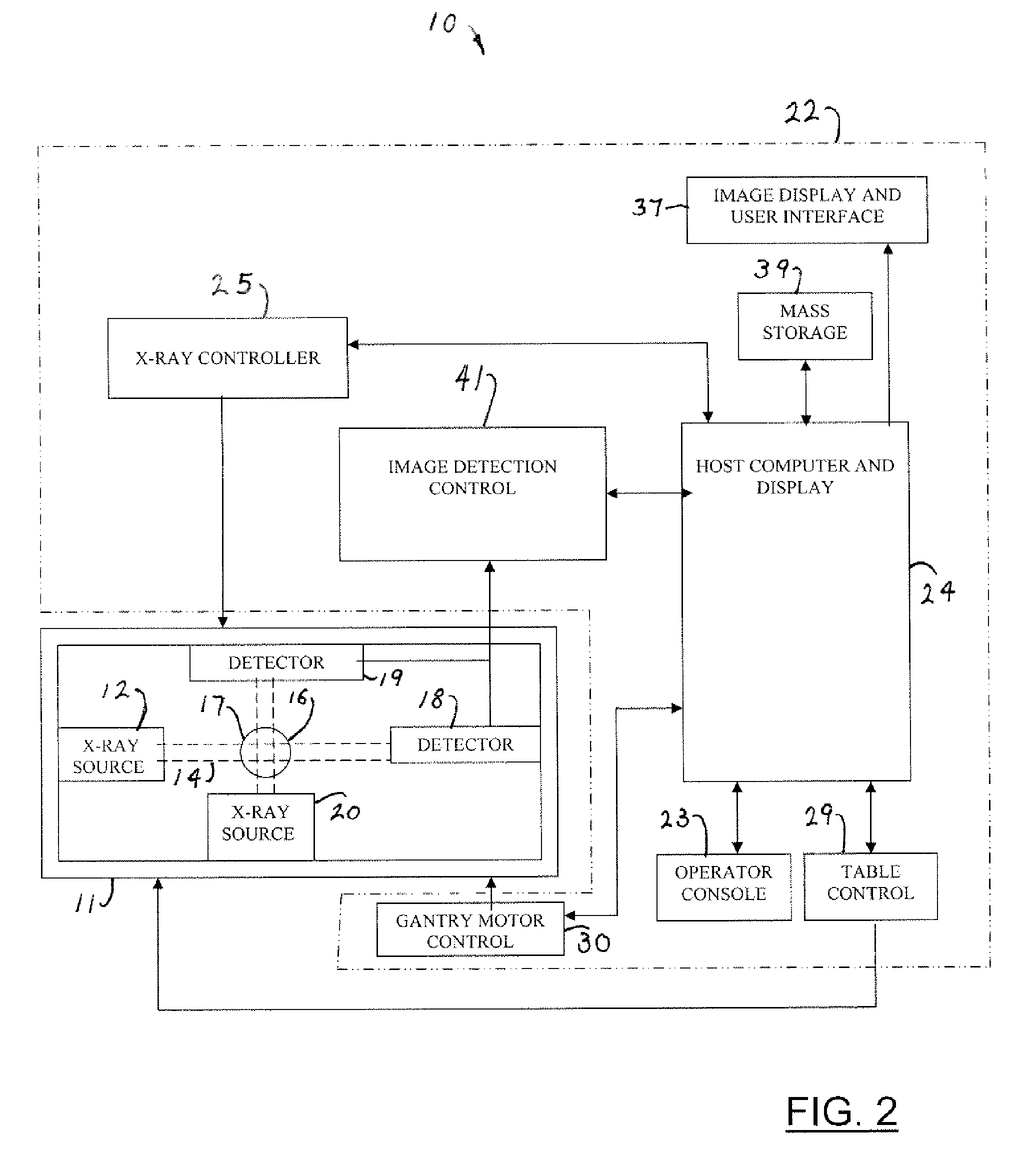
[0024] Referring to FIGS. 1, and 2, a scatter radiation compensation imaging system, including a gantry 11, in accordance with one embodiment of the present invention, is illustrated. A first x-ray source 12, coupled to the gantry 11, generates a first x-ray flux 14, which passes through an object 16 (e.g. a patient) on a table 17 and produces first scatter radiation. The system further includes a first x-ray detector 18 (first detector system), coupled to the gantry 11, which generates a detector signal in response to x-ray flux and scatter signals.

[0025] A second x-ray source 20, also coupled to the gantry 11, genera...


PUM

PropertyMeasurementUnit
currentaaaaaaaaaa
physical conditionaaaaaaaaaa
fixed radiusaaaaaaaaaa

Abstract

A method for x-ray scatter correction during simultaneous bi-plane imaging using digital image processing. The basic concept includes correcting the image from each plane by combining it with an image of the scatter generated from the exposures of the opposite plane in such a way that the scatter effects are removed. The correction image is formed by sampling images from the detector with only the x-ray exposure of the scatter producing plane being active. These sampled images of scatter are processed to form the scatter correction image. The scatter correction image is stored in an image memory so that it is available for combination with subsequent x-ray images to remove scatter distortion.

Description

TECHNICAL FIELD [0001] The present invention relates generally to x-ray systems and more particularly to bi-plane imaging systems. The invention further relates to the generation and transfer of image data generated from bi-plane imaging in conjunction with information systems. [0002] X-ray imaging is a method of taking pictures of the inside or internal portions of an object. (The inside or internal portions of an object are those which are not visible from the exterior of the object with a human eye unless the object is opened to expose the portion of interest.) Such objects may be a human (animal) body, baggage, or vehicles. As the x-ray beam passes through the object, it is absorbed by the varying structure thereof. In the case of a body, such structure would include the bones, tissues and fluid within the body, thereby varying resultant beam intensity. The intensity of the x-ray beam emerging from the object is measured by a device that converts x-ray beam data into a detailed ...

Claims


Application Information

Patent Timeline
Patent Type & Authority Applications(United States)
IPC IPC(8): G01N23/201
CPCA61B6/00
Inventor LAMBERTY, JOHN ROBERTMORROW, JAMES G.
Owner GE MEDICAL SYST GLOBAL TECH CO LLC
Why Eureka
Try Eureka