Printer apparatus

a printing machine and printing technology, applied in the field of printing machines, can solve the problems of lowering cutting quality, high manufacturing cost, and paper jamming, and achieve the effects of low cost structure, simple structure and reliable avoidan

Inactive Publication Date: 2006-04-20
SEIKO INSTR INC
View PDF29 Cites 8 Cited by
  • Summary
  • Abstract
  • Description
  • Claims
  • Application Information

AI Technical Summary

Benefits of technology

[0022] Furthermore, in the printing apparatus, a distance from the thermal-activation thermal head to the cutter device, and a transport speed of the transporting means may be set so that the thermal-activation thermal head is at a temperature equal to or less than the predetermined temperature when the cutting position of the heat-sensitive adhesive sheet reaches the cutter device. Conditions where residual heat at a temperature equal to or greater than the predetermined temperature of the thermal-activation thermal head causes the heat-sensitive adhesive layer of the heat-sensitive adhesive sheet located at the thermal-activation thermal head to activate, or causes the heat-sensitive color-developing layer of the printable surface to develop color when cutting processing of the heat-sensitive adhesive sheet is performed by the cutter device can thus be reliably avoided.
[0023] The printing apparatus further includes thermal head separating means for withdrawing a surface of the thermal-activation thermal head from the heat-sensitive adhesive sheet. In the printing apparatus, the controlling means may stop the transporting means, and may operate the thermal head separating means, when the cutting position of the thermal sensitive adhesive sheet reaches the cutter device. The heat-sensitive adhesive sheet located at the thermal-activation thermal head is thus separated from the thermal-activation thermal head when the cutter device performs cutting processing of the heat-sensitive adhesive sheet. Accordingly, conditions where the heat-sensitive adhesive layer activates or the heat-sensitive color-developing layer of the printable surface develops color due to the thermal-activation thermal head can be more reliably avoided.
[0024] Further, in the printing apparatus, the thermal head separating means may include: an actuated striker member that is provided on a lower surface side of the thermal-activation thermal head and capable of upward and downward movement operation together with the thermal-activation thermal head; and a cam mechanism that contacts a portion of the actuated striker member and converts rotational motion into upward and downward motion. The thermal head separating means can thus be realized by using a simple, low cost structure.
[0025] Furthermore, in the printing apparatus, the thermal head separating means may include: an actuated striker member that is provided on a lower surface side of the thermal-activation thermal head and capable of upward and downward movement operation together with the thermal-activation thermal head; and an actuator that contacts a portion of the actuated striker member and causes the actuated striker member to move upward and downward. The thermal head separating means can thus be realized by using a simple structure.
[0026] It should be noted that in the printing apparatus, the actuator may be one of a solenoid, a pneumatic cylinder apparatus, and a hydraulic cylinder apparatus. Upward and downward motion of the thermal-activation thermal head can thus be easily achieved.
[0027] Further, in the printing apparatus, the cutting position of the heat-sensitive adhesive sheet may be an inactivation position that is separated by a predetermined distance, in a direction that is opposite to a transporting direction, from a position at which activation by the thermal-activation thermal head is completed. The heat-sensitive adhesive layer in the cutting position of the heat-sensitive adhesive sheet thus is not activated, and a condition where the heat-sensitive adhesive adheres to the blade of the cutter device, lowering cutting quality, can thus be avoided.

Problems solved by technology

A problem thus exists in which paper jamming tends to occur because the heat-sensitive adhesive sheet adheres to a platen roller used for printing, and then winds around the platen roller.
There is a problem, however, in that manufacturing costs are high.
There is a danger that the heat-sensitive adhesive that has developed adhesion will adhere to a blade of the cutter device, lowering the cutting quality.
There is a problem in that when applying the heat-sensitive adhesive sheet to an object the areas without adhesion easily peel.
Further, it is necessary to stop transporting the heat-sensitive adhesive sheet when performing cutting by the cutter device, and a thermal head of the thermal activation device has residual heat even after electric power is cut off.
Accordingly, there is a danger that the heat-sensitive adhesive layer of the heat-sensitive adhesive sheet positioned in the thermal activation device will be activated and adhere to the thermal head, and there is a danger that heat will penetrate to the printable surface, resulting in unnecessary color development.

Method used


Image

  • Printer apparatus
  • Printer apparatus
  • Printer apparatus

Examples


first embodiment

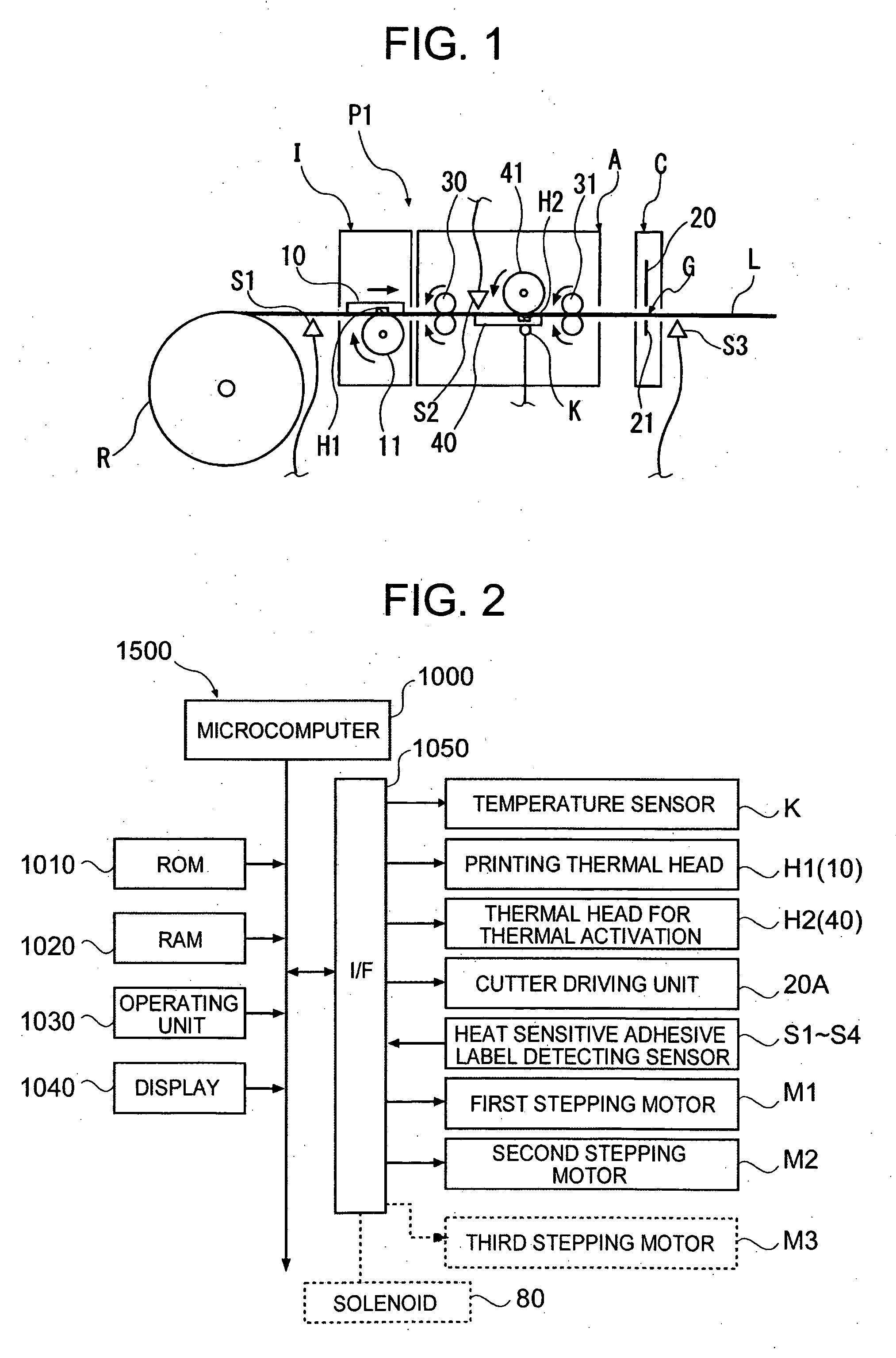
[0040]FIG. 1 is a schematic diagram that shows a configuration of a thermal printer apparatus P1 according to the present invention. FIG. 2 is a control block diagram for the thermal printer P1.

[0041] Referring to FIG. 1, the thermal printer apparatus P1 includes a printer unit I, a thermal activation unit A as a thermal activation device, and a cutter unit C that are disposed in order in a transporting direction (a direction toward the right in FIG. 1) of a heat-sensitive adhesive label L. It should be noted that a heat-sensitive adhesive sheet roll R, around which a continuous sheet of the heat-sensitive adhesive labels L are wound, is disposed in the vicinity of the printer unit I.

[0042] The printer unit I includes a thermal print head 10, a platen roller 11 that is pressed onto the thermal print head 10, and a drive system, which is not shown, that rotates the platen roller 11 (a first stepping motor M1 and a gear train, for example). By rotating the platen roller 11 in a clock...

second embodiment

[0079] Referring to FIGS. 7A to 7D, a thermal printer apparatus P2 according to the present invention is explained next.

[0080] The structure of the thermal printer apparatus P2 is substantially similar to that of the thermal printer apparatus P1 according to the first embodiment, described above. The thermal printer apparatuses differ as follows. The temperature sensor K does not exist in the thermal printer apparatus P2, and the distance from the heater element H2 of the thermal-activation thermal head 40 to the blades 20 and 21 of the cutter unit C has been increased in the thermal printer apparatus P2.

[0081] Referring to FIG. 7A, a distance Y from the heater element H2 of the thermal-activation thermal head 40 to the blades 20 and 21 of the cutter unit C is set so that the thermal-activation thermal head 40 reaches a temperature equal to or less than a predetermined temperature (70° C., for example) when the cutting position G of the heat-sensitive adhesive label L reaches the p...

third embodiment

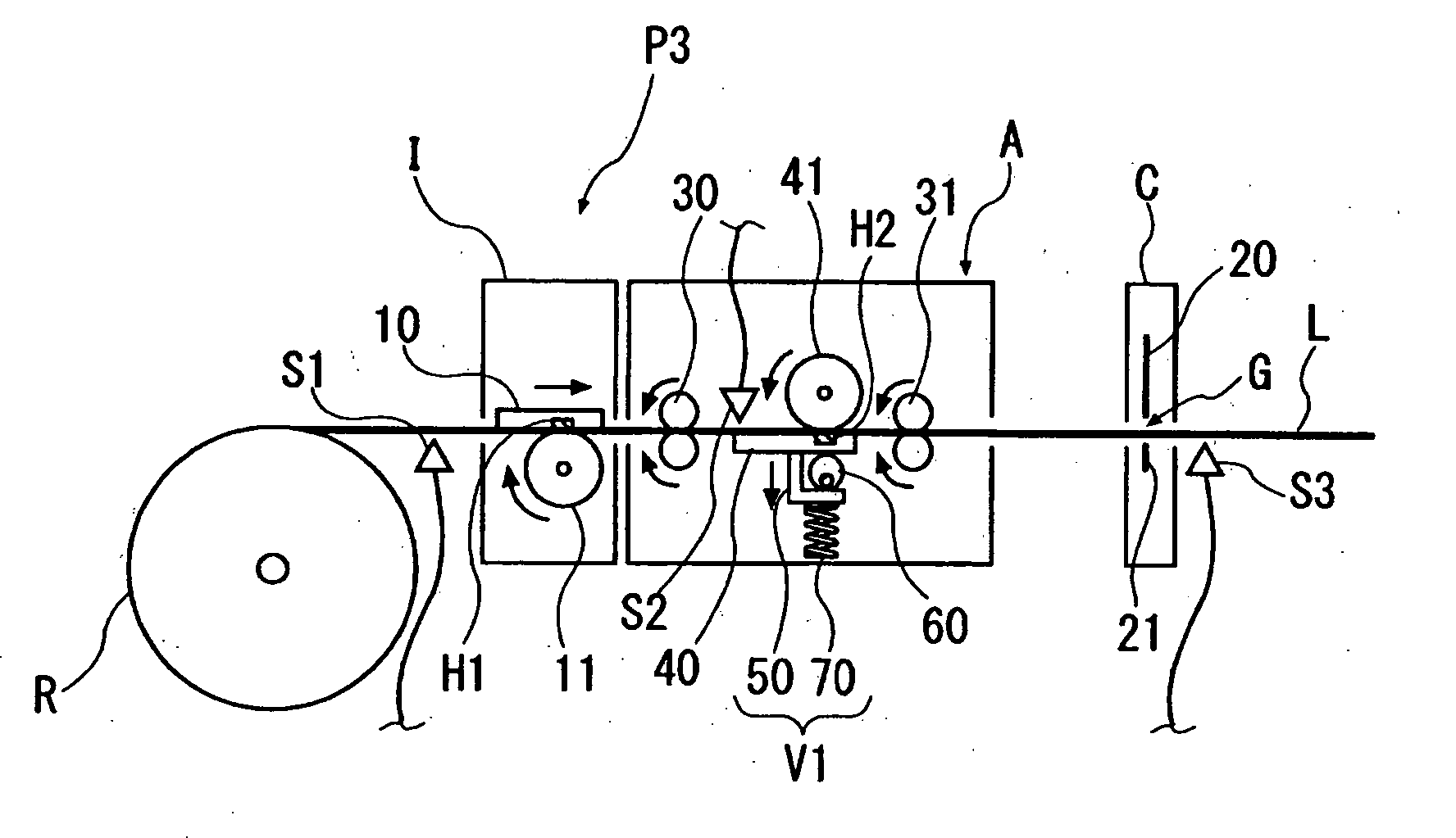
[0085] Referring to FIGS. 8, 9A and 9B, and 10A and 10B, a thermal printer apparatus P3 according to the present invention is explained next.

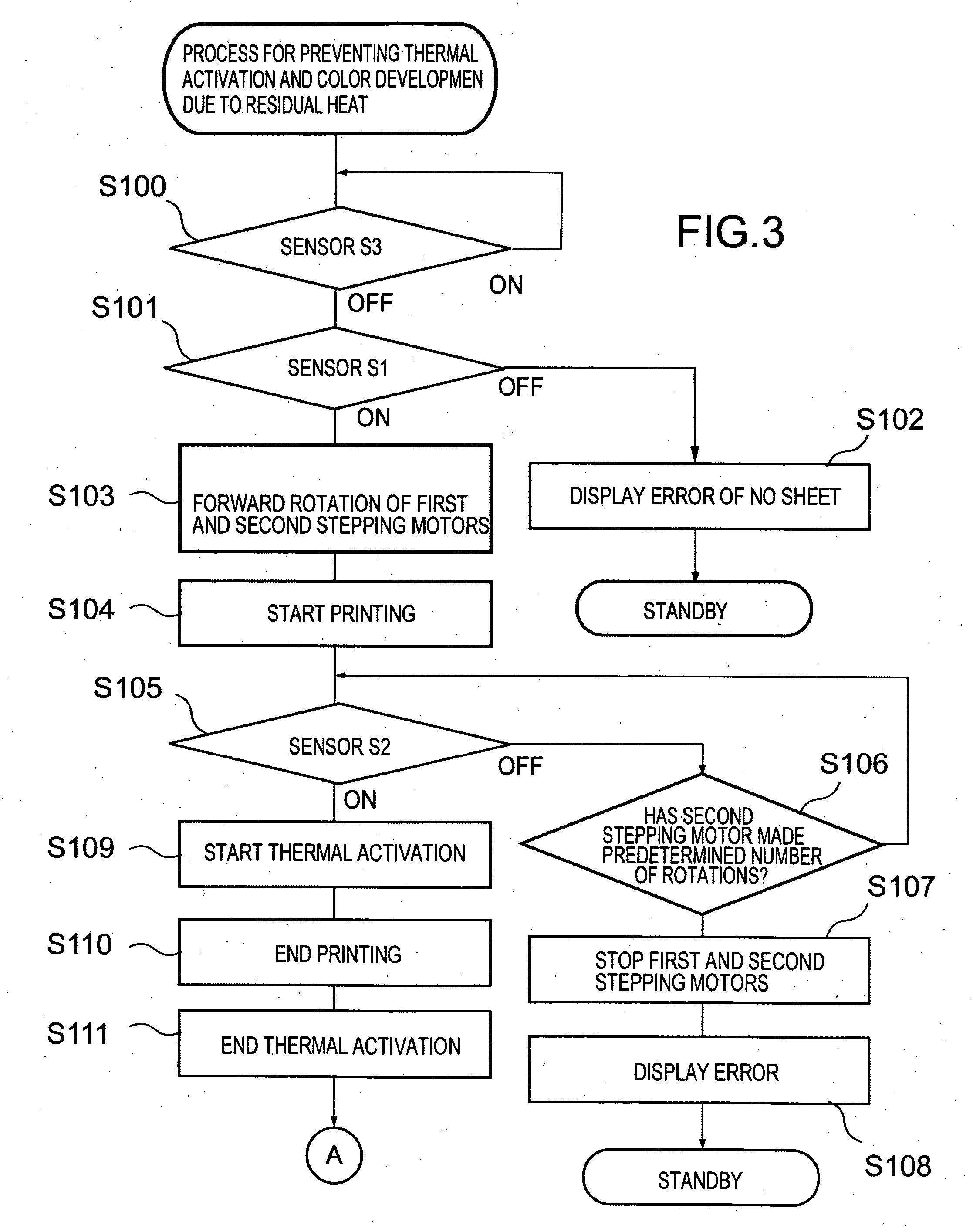
[0086] The thermal printer apparatus P3 according to the third embodiment is configured by omitting the temperature sensor K from the thermal printer apparatus P1 of the first embodiment, and by providing a thermal head separator mechanism V1 that withdraws the thermal-activation thermal head 40 from the thermal activation platen roller 41. The first stepping motor M1 and the second stepping motor M2 are stopped when the cutting position G of the heat-sensitive adhesive label L reaches the position of the blades 20 and 21 of the cutter unit C, and the thermal head separator mechanism V1 is operated. The heat-sensitive adhesive layer of the heat-sensitive adhesive label L located at the thermal-activation thermal head 40 is thus separated from the surface of the thermal-activation thermal head 40 when the cutter unit C performs cutting processin...


PUM


Abstract

Provided is a printer apparatus, including: a thermal print head that performs printing by contacting a heat-sensitive color-developing layer of a heat-sensitive adhesive sheet that includes a printable surface made from the heat-sensitive color-developing layer on one surface of a sheet-like base material, and a heat-sensitive adhesive layer on another surface of the sheet-like base material; a thermal-activation thermal head that activates the heat-sensitive adhesive layer by heating; a cutter device that cuts the heat-sensitive adhesive sheet; a transporting unit that transports the heat-sensitive adhesive sheet; and a controlling unit that controls the thermal print head, the thermal-activation thermal head, and the cutter device. The controlling unit controls the transporting unit to transport the heat-sensitive adhesive sheet so as to pass through the thermal print head, the thermal head used for activation, and the cutter device, in order; and to transport a leading edge of a remainder portion of the heat-sensitive adhesive sheet, after the cutter device cuts the heat-sensitive adhesive sheet, to return to a printing position of the thermal print head or to a heating position of the thermal-activation thermal head.

Description

BACKGROUND OF THE INVENTION [0001] 1. Field of the Invention [0002] The present invention relates to a printer apparatus for a heat-sensitive adhesive sheet in which a heat-sensitive adhesive layer that is normally non-adhesive and exhibits adhesion only when heated is formed on one side of a sheet-like base material. [0003] 2. Description of the Related Art [0004] Thermal activation sheets (print medium in which a coat layer containing a thermal activation component is formed on the surface, for example, heat-sensitive adhesive sheets) have recently become available as sheets to be applied to merchandises, and are used in wide fields. Examples of uses of thermal activation sheets include POS sheets for food products, delivery address sheets, sheets bearing medical information, baggage tags, and labels of bottles and cans. [0005] Those heat-sensitive adhesive sheets are composed of a sheet-like base material (base paper, for example) one side of which has a heat-sensitive adhesive l...

Claims


Application Information

Patent Timeline
Patent Type & Authority Applications(United States)
IPC IPC(8): B41J2/315
CPCB41J2/325
Inventor HOSHINO, MINORUSANBONGI, NORIMITSUOBUCHI, TATSUYASATO, YOSHINORI
Owner SEIKO INSTR INC
Why Eureka
Try Eureka