Wafer chuck

a technology of chuck and chuck body, which is applied in the direction of grinding machine components, grinding drives, manufacturing tools, etc., can solve the problems of unavoidable creation of microscopic defects at the wafer, and achieve the effect of preventing localized distortion or curve of the wafer, preventing easy removal, and not causing defects on the wafer

Inactive Publication Date: 2006-04-20
BBS KINMEI CO LTD
View PDF9 Cites 10 Cited by
  • Summary
  • Abstract
  • Description
  • Claims
  • Application Information

AI Technical Summary

Benefits of technology

[0018] According to the configuration of the present invention, the holding member is driving all together in the closing direction towards the center of the wafer by way of the driving mechanism to push the outer periphery of the wafer in the radial direction and mechanically hold the wafer. That is, in such state, since the wafer is held with both surfaces floating in the air, even if slurry produced when polishing the orientation notch or orientation flat of the outer peripheral part is attached, the slurry can be easily removed in the post-process of washing and the like, and thus does not cause defects on the wafer. When a plurality of holding members are driven parallel to the wafer all together by the same stroke towards the center of the wafer by way of the driving mechanism, each holding member applies the same pushing force parallel to both surfaces of the wafer towards the central part of the wafer in the thickness direction, thereby preventing localized distortion or curve of the wafer.
[0019] Each holding member holds the wafer by way of the elastic m

Problems solved by technology

According to the conventional technique, when slurry (mixture of fluid polishing agent containing abrasive grain and powder polishing waste of the wafer) enters the low

Method used


Image

  • Wafer chuck
  • Wafer chuck
  • Wafer chuck

Examples


Embodiment Construction

[0030] The embodiments of the present invention will now be described with reference to the drawings.

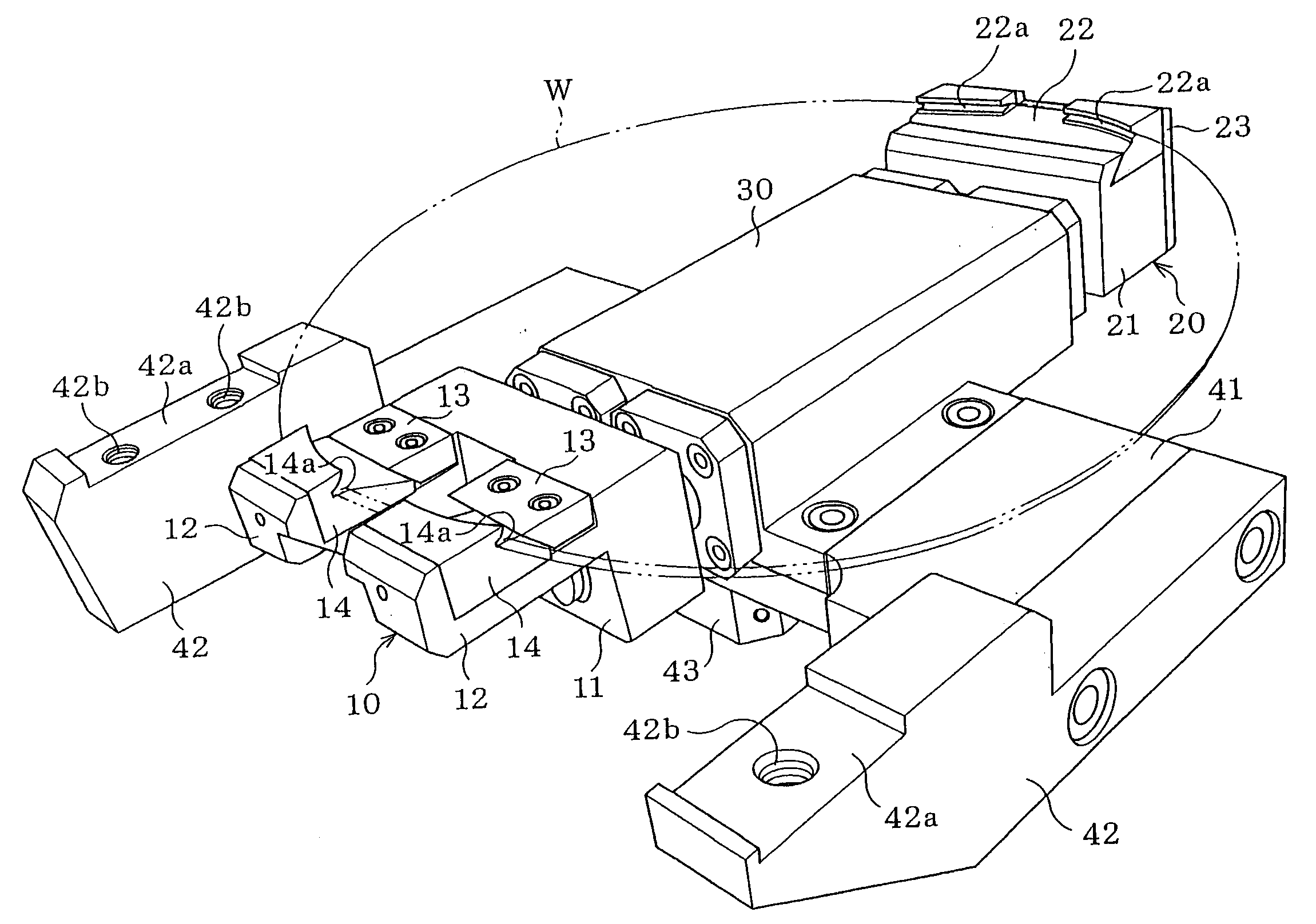
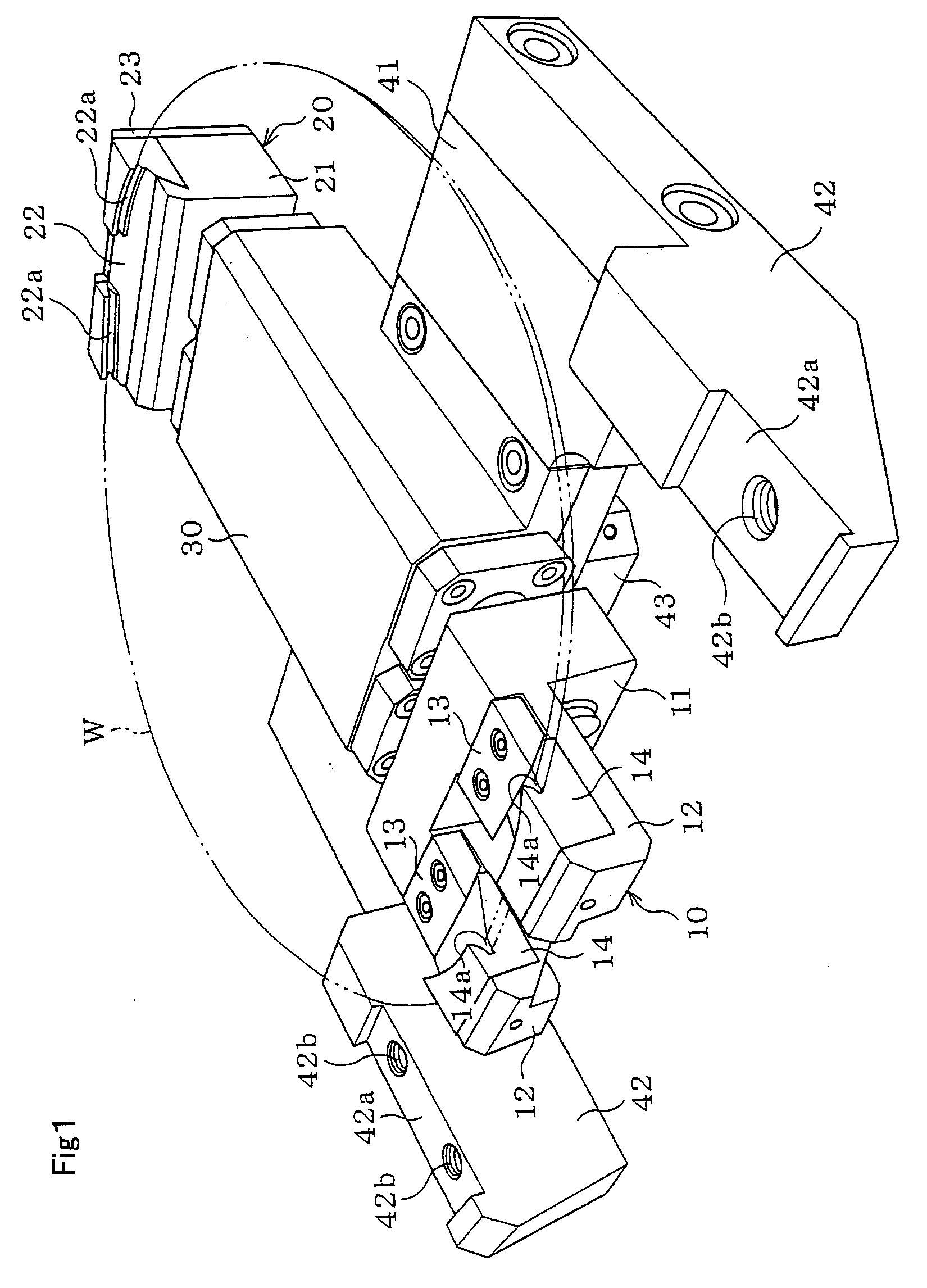
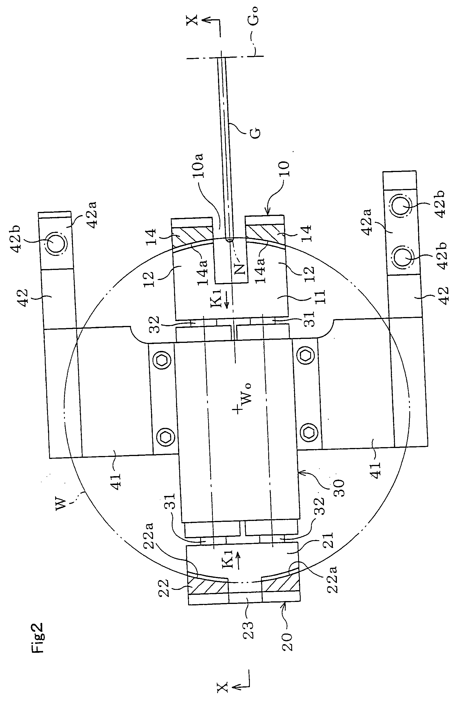
[0031] The wafer chuck is made by integrally assembling a pair of holding members 10, 20 and a driving mechanism 30 (FIG. 1, FIG. 2). The holding members 10, 20 are driven in a closing direction-(direction of arrow K1, K1 of FIG. 2) by way of the driving mechanism 30 to push the outer periphery of the wafer W towards the center Wo of the wafer W in a radial direction and hold the wafer W.

[0032] One of the holding members 10 is formed with a pair of left and right parallel fingers 12, 12 projecting horizontally from a distal end of the common base 11. The distal end of each finger 12 is bent upwards, and an elastic member 14 is attached in an exchangeable manner to the upper surface of each finger 12 by way of a press plate 13. V-shaped grooves 14a that conforms to the outer peripheral part of the wafer W is formed at each elastic member 14, 14, and the V-shaped grooves 14a, 14a, op...


PUM


Abstract

The influence of the slurry generated when polishing an orientation notch and the like is minimized. The holding members 10, 20 for holding the outer periphery of the wafer W and the driving mechanism 30 for driving the holding members 10, 20 all together in the closing direction are integrally combined.

Description

BACKGROUND OF THE INVENTION [0001] 1. Field of the Invention [0002] The present invention relates to wafer chucks suitably used particularly when polishing an orientation notch and the like of the outer periphery part of the semiconductor wafer. [0003] 2. Description of the Related Art [0004] The semiconductor wafer (hereinafter referred to simply as a wafer) has a V-shaped or a circular arc shaped orientation notch formed on the outer periphery. It is to be noted that the notch may be a linear orientation flat. [0005] When forming the orientation notch in the wafer, the polishing pad contacts the outer periphery of the wafer along a predetermined trajectory so as to create a predetermined angle, which wafer is normally attracted to and fixed to the vacuum chuck that uses vacuum, (e.g., Japanese Laid-Open Patent Publication No. 2-180554 and Japanese Laid-Open Patent Publication No. 2002-28840.). That is, a concentric or a radial groove communicating to the vacuum source is formed on...

Claims


Application Information

Patent Timeline
IPC IPC(8): B24B47/00
CPCB24B9/065B24B41/067
Inventor YOSHIDA, TAKASHIMURAKAMI, SHINICHIITOU, HIROYUKI
Owner BBS KINMEI CO LTD
Why Eureka
Try Eureka