Golf club head having a cushion channel formed with a varied width and manufacturing method therefor

Inactive Publication Date: 2006-04-20
FUSHENG IND CO LTD
View PDF11 Cites 7 Cited by
  • Summary
  • Abstract
  • Description
  • Claims
  • Application Information

AI Technical Summary

Benefits of technology

[0009] The primary objective of this invention is to provide a golf club head having a cushion channel and a manufacturing method therefor, wherein the cushion channel is provided between an inner periphery of a through hole of a main body and an outer periphery of a carbon-fiber plate to form a clearance with an appropriate varied with for absorbing deformation to reduce the wrinkles and the influence thereof on the entire structural strength.
[0010] The secondary objective of this invention is to provide the golf club head having the cushion channel and the manufacturing method therefor, wherein the cushion channel is provided between the through holes of the main body and the carbon-fiber plate, and is filled with elastic colored filler to enhance the appearance of the final product.
[0011] The manufacturing method for the golf club head in accordance with an aspect of the present invention comprises the steps of: forming a through hole on a surface of a main body; preparing a carbon-fiber plate formed by carbon-fiber fabrics; providing a cushion channel between an inner periphery of the through hole and an outer periphery of the carbon-fiber plate when assembled, and permitting the cushion channel to form a varied width; filling filler into the varied width of the cushion channel; precision finishing the surface of the main body to thereby produce the final product of the golf club head.
[0016] In a yet further separate aspect of the present invention, the cushion channel of the golf club head is filled with filler for enhancing the appearance of the final product.

Problems solved by technology

Since the main body is generally made of metal, the center of gravity and the total weight of the main body cannot be effectively and specifically adjusted.
By manufacturing such large-size carbon-fiber portion, it has sophisticated the manufacture processes of the prepared carbon-fiber fabrics and prolonged the manufacture time.
In manufacture operation of the carbon-fiber plate, it reduces the product quality due to irregular and uncontrollable deformation of the prepared carbon-fiber fabrics in nature.
Moreover, a large area of the prepared carbon-fiber fabrics may weaken the entire structural strength of the main body, and it may further make a lower striking sound instead of a sharp striking sound naturally made by a metal golf club head.

Method used


Image

  • Golf club head having a cushion channel formed with a varied width and manufacturing method therefor
  • Golf club head having a cushion channel formed with a varied width and manufacturing method therefor
  • Golf club head having a cushion channel formed with a varied width and manufacturing method therefor

Examples


first embodiment

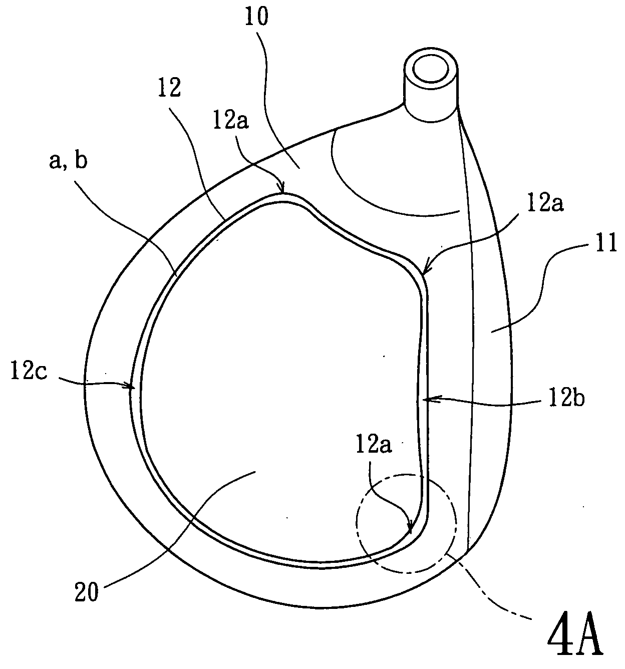
[0037] Referring to FIGS. 3, 4 and 4A, the first step of the manufacture method in accordance with the present invention is forming a plurality of through holes 12 on the surface of the main body 10 of the golf club head. The main body 10 is preferably formed as a single one-piece member by casting and the material thereof can be selected from a group consisting of stainless steel, titanium alloy, and iron etc. Generally, a striking plate 11 is attached to the front of the main body 10 by welding, integrally forming or embedding. An appropriate amount of the through holes 12 are formed on the crown plate, the sole plate or the side plate of the main body 10. A stepped portion 121 is formed on the peripheral of the through holes 12 for supporting a carbon-fiber plate 20, a weighting member 30 and a nameplate 40 (as shown in FIG. 1), which are constructed from predetermined sizes, in the following procedure.

[0038] Referring to FIGS. 3, 4 and 4A, the second step of the manufacture meth...

second embodiment

[0048] Furthermore, as shown in FIGS. 11, 11A, 12 and 12A, when the size of the through holes 12 and the carbon-fiber plate 20 is too large to form a predetermined longer distance of the cushion channel “a”, a number of disadvantage limitations exist for a CNC milling process in milling the periphery of the through holes 12 and the carbon plate 20. Alternatively, a first stepped portion 122 and a second stepped portion 123 of the second embodiment in the present invention, as best shown in FIG. 7, can be used to position the large-size carbon-fiber plate 20 on the large-size through holes 12 so as to form a desired, predetermined longer distance of the cushion channel “a” varying in width.

[0049] Advantageously, the stepped portion 122 of the through hole 12 conveniently receives the carbon-fiber plate 20 such that the large-size carbon-fiber plate 20 is adhered to the first stepped portion 122 of the through hole 12 for the ease of manufacture. Meanwhile, the second stepped portion ...

third embodiment

[0053] As shown in FIGS. 11, 11A, 12 and 12A, the short fingers 21 of the carbon-fiber plate 20 in the third embodiment can also be adapted to support a large-size carbon-fiber plate 20 on a large-size through hole 12 for forming cushion channel “a” with various widths.

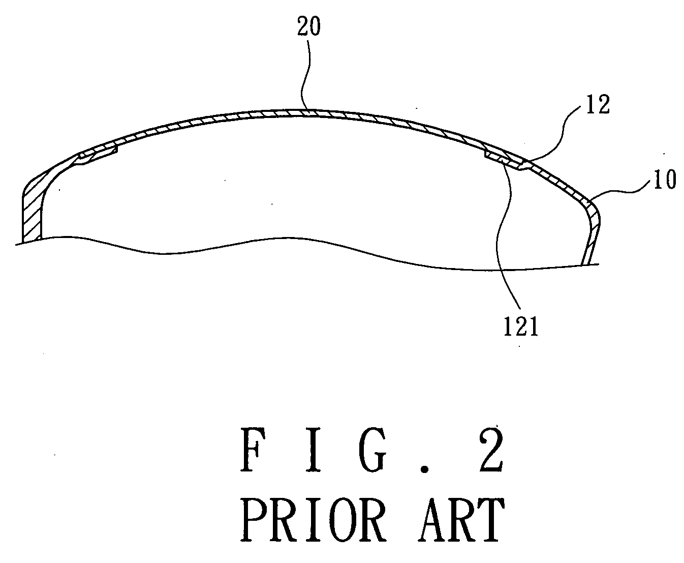
[0054] As has been described above, the conventional carbon-fiber plate 20 is closely fitted with the through hole 12 on the main body 10, thereby plastic deformation and wrinkles occur constantly, as shown in FIGS. 1 and 2. However, the golf club head and the manufacture method therefor in the present invention indeed maintain the structural strength of the main body 10 and promote the quality and the product price.


PUM


Abstract

A golf club head includes a cushion channel varying in width. The manufacturing method therefor includes the steps of: forming a through hole on a surface of a main body; preparing a carbon-fiber plate formed by carbon-fiber fabrics; providing the cushion channel between an inner periphery of the through hole and an outer periphery of the carbon-fiber plate when assembled, and permitting the cushion channel to form a varied width; filling filler into the varied width of the cushion channel; precision finishing the surface of the main body to thereby produce the final product of the golf club head.

Description

CROSS REFERENCE TO RELATED APPLICATION [0001] This application is a continuation-in-part application of U.S. patent Ser. No. 10 / 423,989, filed on Apr. 28, 2003.BACKGROUND OF THE INVENTION [0002] 1. Field of the Invention [0003] The present invention relates to a golf club head having a cushion channel and a manufacturing method therefor. Particularly, the present invention relates to the cushion channel formed between a through hole of a main body of the golf club head and a prepared carbon fiber plate. More particularly, the present invention relates to an elastic colored filler filled in the cushion channel to prevent from the occurrence of wrinkles or deformation on peripheries of the through holes and the carbon fiber plates. [0004] 2. Description of the Related Art [0005] A conventional golf club head mainly includes a main body and a striking plate attached thereto, all of which are made of metal or alloy. The main body is integrally formed as a one-piece single member by cast...

Claims


Application Information

Patent Timeline
IPC IPC(8): A63B53/04
CPCA63B53/0466A63B2053/0416A63B2053/0437A63B2209/00A63B2209/023A63B2053/0491A63B53/0416A63B53/0437A63B60/02
Inventor CHEN, YUN-FANG
Owner FUSHENG IND CO LTD
Why Eureka
Try Eureka