Eureka AIR delivers breakthrough ideas for toughest innovation challenges, trusted by R&D personnel around the world.

Minimally invasive method and apparatus for fusing adjacent vertebrae

a minimally invasive and adjacent vertebrae technology, applied in the field of minimally invasive methods and apparatuses for fusing adjacent vertebrae, can solve the problems of pseudoarthrosis, post-operative stability, and other known spinal fixation and/or fusion procedures can be quite invasive, traumatic and time-consuming,

Inactive Publication Date: 2006-04-20
THE CLEVELAND CLINIC FOUND
View PDF14 Cites 253 Cited by
  • Summary
  • Abstract
  • Description
  • Claims
  • Application Information

AI Technical Summary

Benefits of technology

[0006] In accordance with additional aspects of the inventive method, wherein prior to said step of securing the second block member of the swivel block assembly relative to the first block member to achieve a desired angle for the first axis, the cannula is moved to aim the cannula toward the facet joint on the second side of the vertebrae along a second axis. Percutaneous access along the second axis is then obtained to the facet joint on the second side via the cannula and a bone graft material is placed into the facet joint on the second side through the cannula to assist with fusion of the upper and lower vertebrae.
[0008] In accordance with additional aspects of the inventive method, the cannula is moved to aim the cannula along a fourth axis toward the facet joint on the first side previously secured with the first screw. Percutaneous access to the facet joint on the first side is obtained via the cannula and a bone graft material is placed through the cannula into the facet joint around the previously implanted first screw to assist with fusion of the upper and lower vertebrae.

Problems solved by technology

These and other known spinal fixation and / or fusion procedures can be quite invasive, traumatic, and time consuming.
Further, problems with post-operative stability and pseudoarthrosis are often associated with many of these procedures.

Method used


Image

  • Minimally invasive method and apparatus for fusing adjacent vertebrae
  • Minimally invasive method and apparatus for fusing adjacent vertebrae
  • Minimally invasive method and apparatus for fusing adjacent vertebrae

Examples


Embodiment Construction

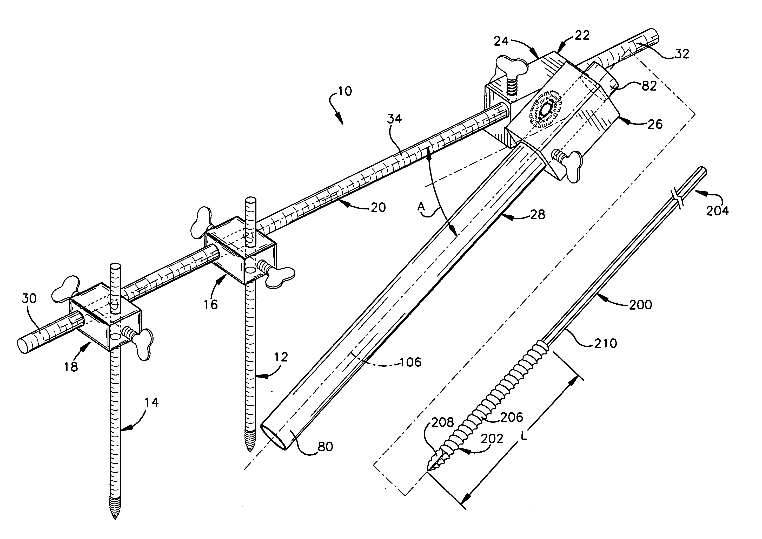
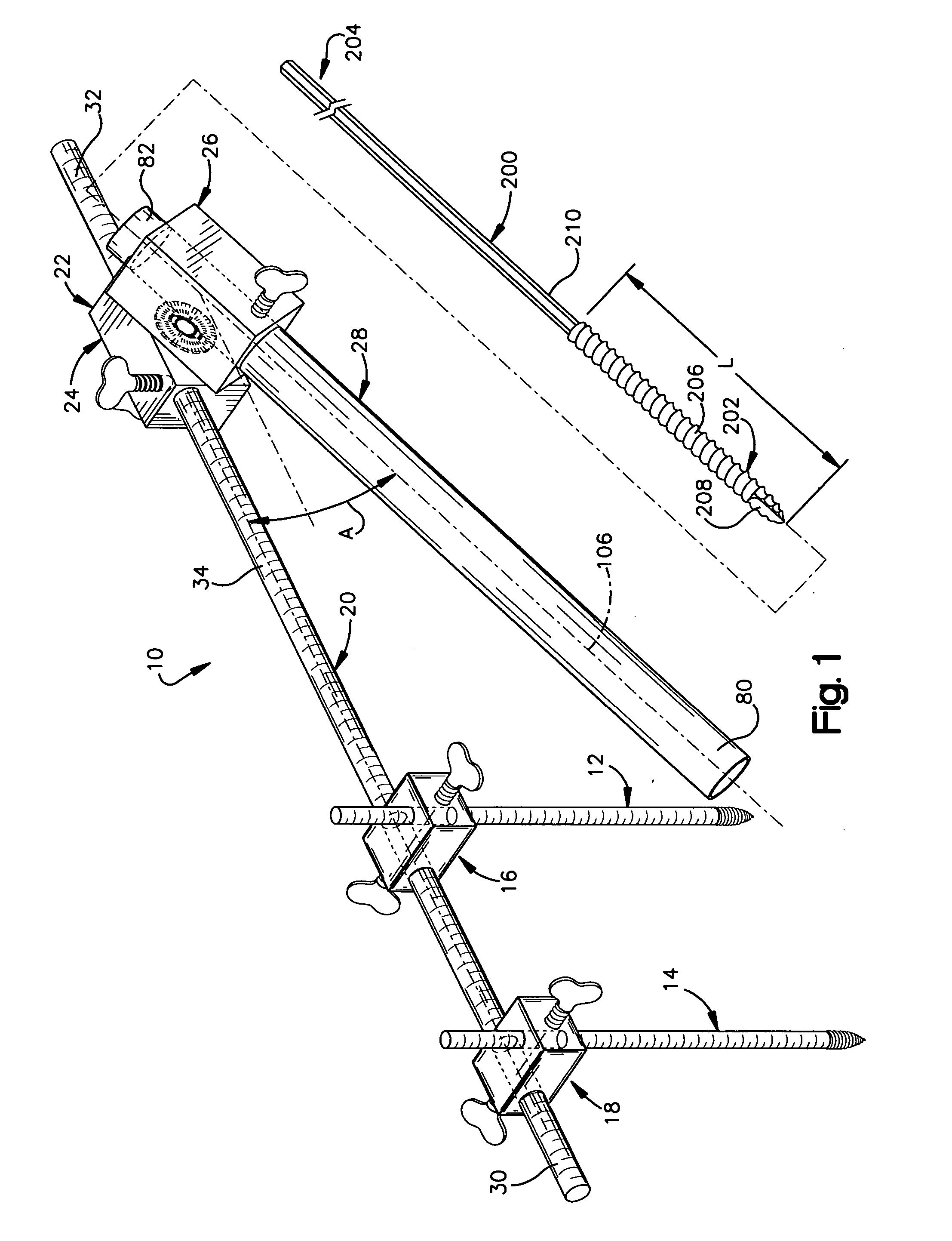
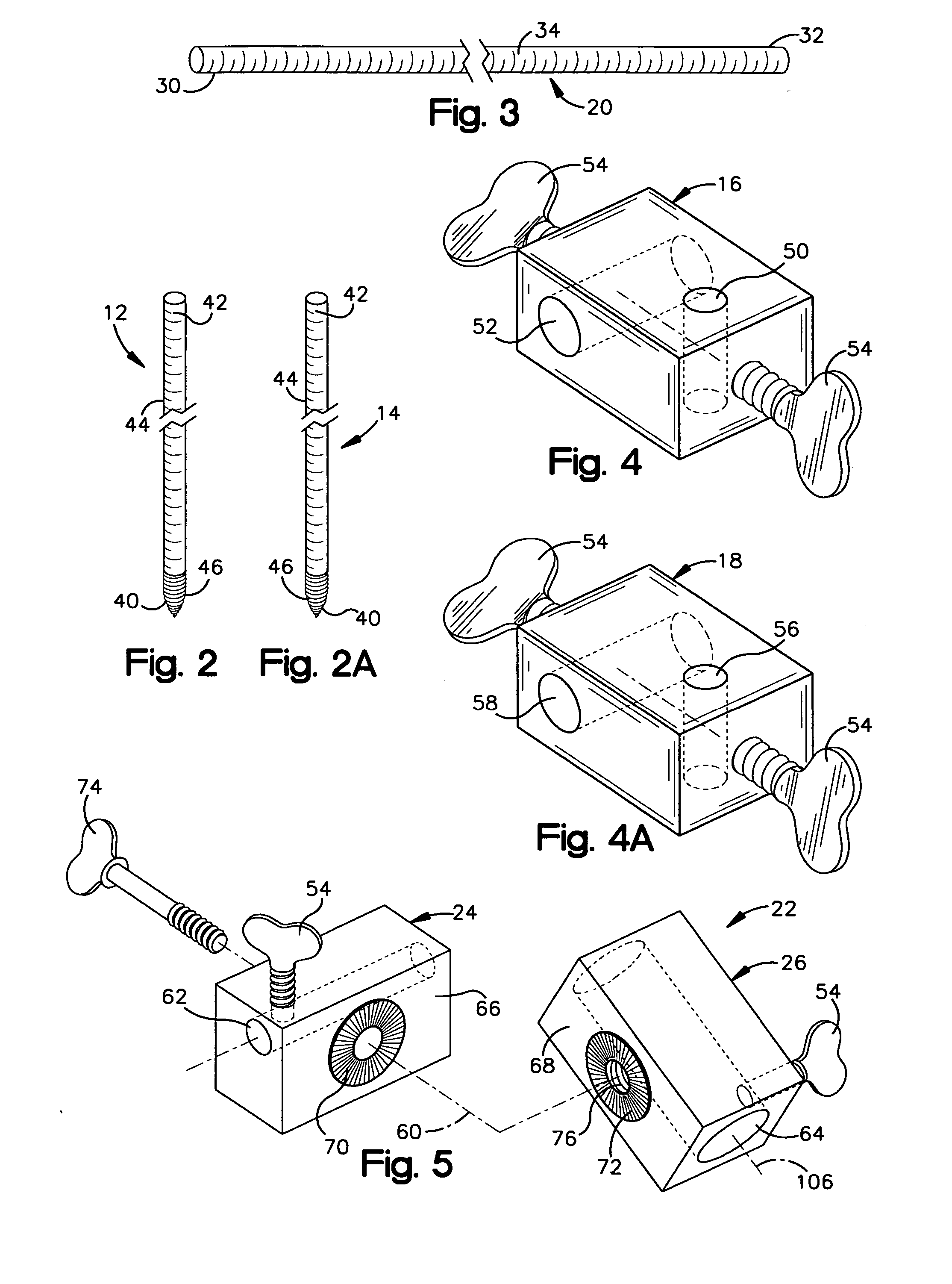
[0047] The present invention relates to a minimally invasive method and apparatus for fusing adjacent vertebrae. As representative of the present invention, FIG. 1 illustrates an apparatus 10 comprising first and second Kirschner wires 12 and 14 (commonly referred to as “K-wires”), first and second fixation blocks 16 and 18, a rod member 20, a swivel block assembly 22 comprising first and second block members 24 and 26, a cannula 28, and at least one removable screw 200.

[0048] As may be seen in FIG. 3, the rod member 20 is a cylindrical component that may be hollow or solid and is made from any suitable metal or plastic. The rod member 20 has oppositely disposed first and second ends 30 and 32 and an outer diameter of 4 to 7 mm. The rod member 20 includes an outer surface 34 with graduations for measuring axial distances along its length. It is contemplated that other means for measuring axial length along the rod member 20 could also be used.

[0049] The first and second K-wires 12...


PUM


Abstract

The present invention is a minimally invasive surgical method for fusing adjacent vertebrae. A first K-wire is inserted into the spinous process of an upper vertebrae. A second K-wire is inserted into a transverse process of a lower vertebrae. A first fixation block is secured to the first K-wire and a second fixation block is secured to the second K-wire. A rod member extends across the K-wires. A swivel block assembly is secured to achieve a desired angle for a first axis along which a first screw will be implanted into a facet joint. The swivel block assembly is secured at a desired axial position on the rod member. Percutaneous access to the upper vertebrae along the first axis is then obtained via a cannula. A removable screw having a threaded section for implantation across the facet joint and an elongated shank section that is shearable subcutaneously is inserted through the cannula. The threaded section is implanted along the first axis across the facet joint to attach the upper and lower vertebrae. A shearing tool is inserted percutaneously over the shank section and the shank section is sheared off immediately above the lamina.

Description

TECHNICAL FIELD [0001] The present invention relates to a minimally invasive method and apparatus for fusing adjacent vertebrae. BACKGROUND OF THE INVENTION [0002] Over 200,000 spinal fixation and spinal fusion procedures are performed annually to correct various congenital and degenerative spinal disorders in humans. Many of these corrective surgical procedures are performed in the lumbar and lumbosacral regions of the spine where traumatic and age-related disc degeneration is common. One such procedure involves the implantation of spinal fixation instrumentation, including plates and rods, using pedicle screws. Another procedure involves the implantation of one or more anterior fusion cages into the intervertebral disc space following a discectomy. These and other known spinal fixation and / or fusion procedures can be quite invasive, traumatic, and time consuming. Further, problems with post-operative stability and pseudoarthrosis are often associated with many of these procedures....

Claims


Application Information

Patent Timeline
IPC IPC(8): A61B17/56
CPCA61B17/1757A61B17/7053A61B17/7064A61B17/863A61B17/8863A61B2019/307A61B2019/461A61B2019/462A61B2090/037A61B2090/061A61B2090/062
Inventor LIEBERMAN, ISADOR H.
Owner THE CLEVELAND CLINIC FOUND
Why Eureka
Eureka Blog
Learn More