Dehumidifying element, and adsorbing element used for the dehumidifying element

a technology of dehumidification element and adsorption element, which is applied in the field of dehumidification units, can solve the problems of affecting the dehumidification capability of the dehumidification unit, and achieve the effects of improving the performance of heat transfer between the air ventilation passages 3, 4 and cost saving

Inactive Publication Date: 2006-04-27
DAIKIN IND LTD
View PDF8 Cites 31 Cited by
  • Summary
  • Abstract
  • Description
  • Claims
  • Application Information

AI Technical Summary

Benefits of technology

[0024] By virtue of the above-described arrangements, the present invention provides the following effects.
[0025] (a) The first invention of the present application discloses a dehumidification unit comprising alternate laminations of an adsorption element 1 which supports an adsorbent and which is provided with a first air ventilation passage 3 through which air (Aa) to be processed is passed, and a cooling element 2 which is provided with a second air ventilation passage 4 through which cooling air (Ab) is passed, wherein the first air ventilation passage 3 of the adsorption element 1 and the second air ventilation passage 4 of the cooling element 2 are adjacently formed, with a single plate member P lying between the first air ventilation passage 3 and the second air ventilation passage 4. As a result of such arrangement, the performance of heat transfer between the air ventilation passages 3, 4 is further improved as compared with a conventional construction in which the air ventilation passages 3, 4 are adjacently formed, with two sheets of plates laying therebetween, and the action of absorption and removal of heat of adsorption by the cooling air (Ab) is promoted. As a result, the dehumidification capability of the dehumidification unit will be maintained at high levels over a long period of time, thereby contributing to accomplishing improvement in commercial value of the dehumidification unit.
[0026] Furthermore, because of the construction that only a single plate member (i.e., the plate member P) is interposed between the first air ventilation passage 3 of the adsorption element 1 and the second air ventilation passage 4 of the cooling element 2, the dehumidification unit is made compact in size relative to its height direction (i.e., the lamination direction of the adsorption element 1 and the cooling element 2) by an amount corresponding to reduction in the number of plate members lying between the first and second air ventilation passages 3, 4, and cost savings are provided because of reduction in the number of component members.
[0027] (b) The second invention of the present application discloses a dehumidification unit according to the first invention in which the plate member P is a side-plate member 12 which is made of fiber paper and which constitutes a side wall of the adsorption element 1 relative to the lamination direction thereof, and that the side-plate member 12 directly faces the second air ventilation passage 4 of the cooling element 2 and, in addition, a separation sheet layer 14 configured to prevent the flow of gas and liquid is provided on a surface of the side-plate member 12 on the side of the second air ventilation passage 4. As a result of such arrangement, in spite of employing such a construction that the air ventilation passages 3, 4 are separated from each other by the side-plate member 12 made of fib...

Problems solved by technology

This results in inviting a drop in the dehumi...

Method used


Image

  • Dehumidifying element, and adsorbing element used for the dehumidifying element
  • Dehumidifying element, and adsorbing element used for the dehumidifying element
  • Dehumidifying element, and adsorbing element used for the dehumidifying element

Examples


embodiment 1

I. Embodiment 1

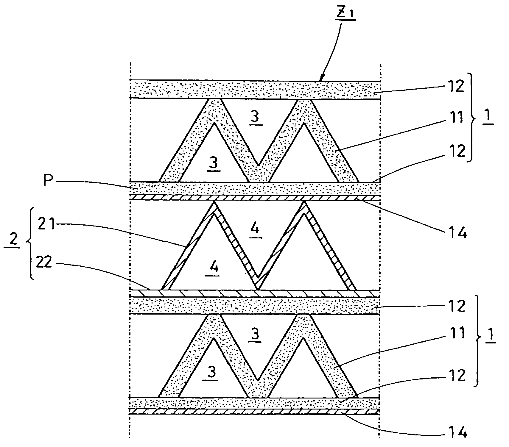
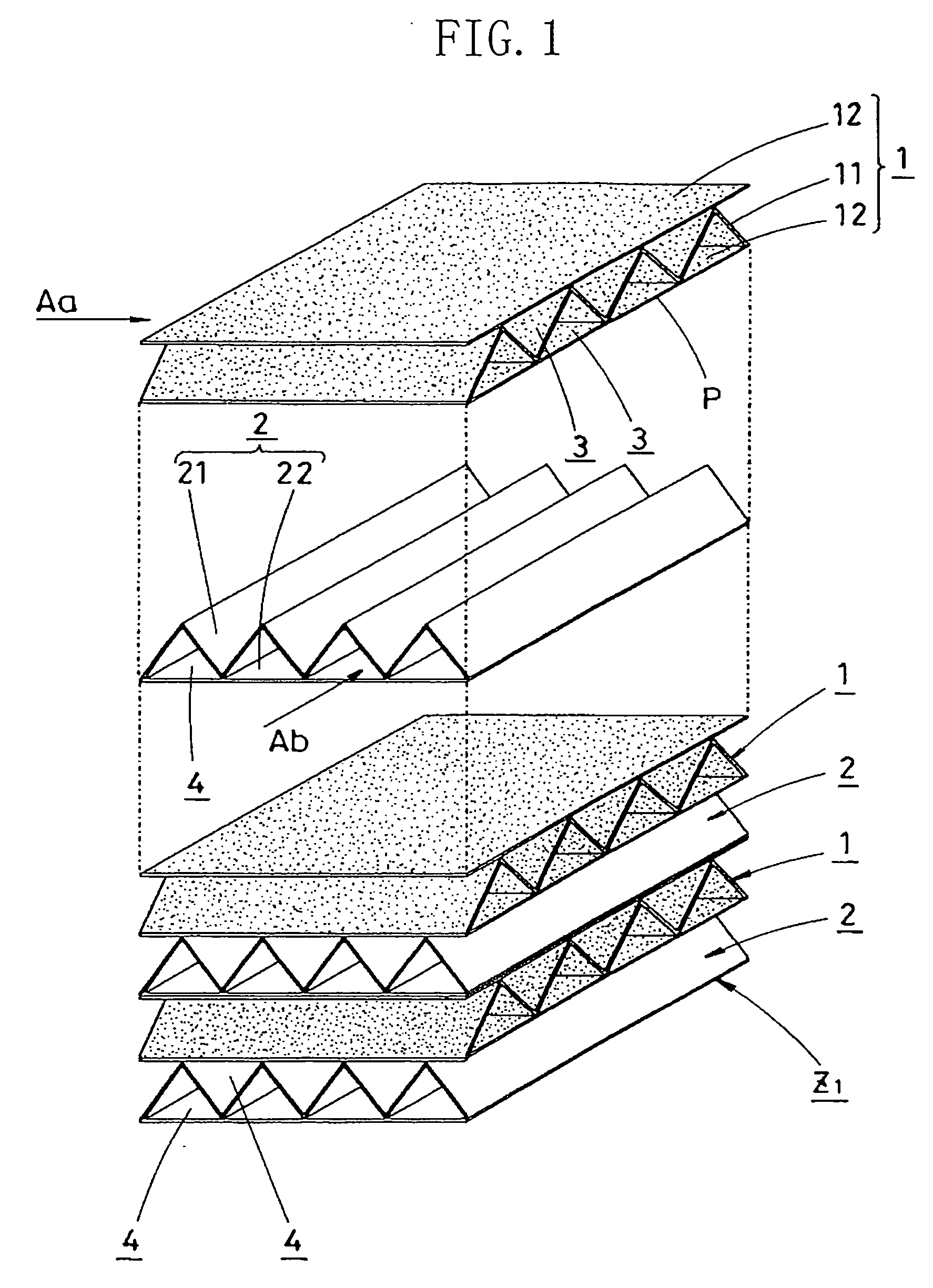
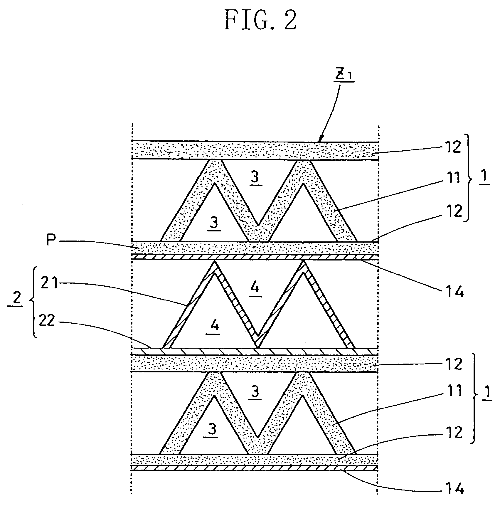
[0069] Referring to FIGS. 1-3, there is illustrated a dehumidification unit Z1 formed in accordance with a first embodiment of the present invention. The dehumidification unit Z1 is the result of the application of inventions as set forth in claim 1, claim 2, claim 5, and claim 8. As shown in FIG. 1, the dehumidification unit Z1 is formed in the following way. A plurality of adsorption elements 1, 1, . . . and a plurality of cooling elements 2, 2, . . . are laminated sequentially alternately in a 90-degree plane phase. Then, such a laminated body is provided, at its both ends relative to the lamination direction, with end plates 9, 9, as shown in FIG. 3. Two end plates 9, 9 are connected together by four frame members 10, 10, . . . which are arranged along the four corners of the laminated body, whereby these components are combined into a single piece. Hereinafter, specific constructions for the adsorption element 1 and the cooling element 2 will be described.

[0070]...

embodiment 2

II. Embodiment 2

[0086] Referring to FIGS. 4 and 5, there is illustrated a dehumidification unit Z2 formed in accordance with a second embodiment of the present invention. The dehumidification unit Z2 is the result of the application of inventions as set forth in claim 1, claim 2, claim 3, claim 5, and claim 8. As can be seen from FIG. 4, the dehumidification unit Z2 is formed by sequentially alternately laminating a plurality of adsorption elements 1, 1, . . . and a plurality of cooling elements 2, 2, . . . one upon the other in a 90-degree plane phase. The dehumidification unit Z2 of the present embodiment is identical in basic construction with the dehumidification unit Z1 of the first embodiment, with the exception that the adsorption element 1 of the dehumidification unit Z2 differs in construction from the adsorption element 1 of the dehumidification unit Z1.

[0087] To sum up, in the adsorption element 1 of the dehumidification unit Z1 according to the first embodiment, the sid...

embodiment 3

III. Embodiment 3

[0092] Referring to FIGS. 6 and 7, there is illustrated a dehumidification unit Z3 formed in accordance with a third embodiment of the present invention. The dehumidification unit Z3 is the result of the application of inventions as set forth in claim 1, claim 2, claim 5, and claim 8. As shown in FIG. 6, the dehumidification unit Z3 is formed by sequentially alternately laminating a plurality of adsorption elements 1, 1, . . . and a plurality of cooling elements 2, 2, . . . one upon the other in a 90-degree plane phase. The dehumidification unit Z3 of the present embodiment is identical in basic construction with the dehumidification unit Z1 of the first embodiment, with the exception that they differ from each other in construction of the adsorption element 1 as well as in construction of the cooling element 2.

[0093] The adsorption element's construction difference is pointed out. For the case of the adsorption element 1 of the dehumidification unit Z1 according t...


PUM

PropertyMeasurementUnit
Thicknessaaaaaaaaaa
Electrical resistanceaaaaaaaaaa
Heightaaaaaaaaaa

Abstract

In a dehumidification unit comprising alternate laminations of an adsorption element (1) which supports an adsorbent and which is provided with a first air ventilation passage (3) and a cooling element (2) which is provided with a second air ventilation passage (4), the first air ventilation passage (3) of the adsorption element (1) and the second air ventilation passage (4) of the cooling element (2) are adjacently formed, with a single plate member (P) lying between the first and second air ventilation passages (3, 4). As a result of such arrangement, as compared with a structure in which the air ventilation passages (3, 4) are adjacently formed with two plate members lying therebetween, the performance of heat transfer between the air ventilation passages (3, 4) is further improved, and the action of absorbing and removing heat of adsorption is promoted, whereby the dehumidification capability of the dehumidification unit is maintained at high levels over a long period of time. Furthermore, the dehumidification unit is made compact relative to its height direction by an amount corresponding to reduction in the number of plate members lying between the first air ventilation passage (3) and the second air ventilation passage (4), and cost savings are provided because of reduction in the number of component members.

Description

TECHNICAL FIELD [0001] This invention relates to a dehumidification unit for the dehumidification of humid air by making utilization of the adsorptive action of an adsorbent. The present invention relates also to an adsorption element for use in such a dehumidification unit. BACKGROUND ART [0002] Dehumidification units making utilization of the adsorptive action of an adsorbent have been known in the prior art. Referring to FIGS. 19 and 20, there is shown a structure of such a conventional dehumidification unit by way of example. [0003] The conventional dehumidification unit Z0 is formed by sequentially laminating an adsorption element 31 having a large number of air ventilation passages 35, 35, . . . each supporting on its interior surface an adsorbent, and a cooling element 41 having a large number of air ventilation passages 45, 45, . . . in a 90-degree plane phase so that the air ventilation passages 35 are approximately orthogonal to the air ventilation passages 45. [0004] And,...

Claims


Application Information

Patent Timeline
IPC IPC(8): B01D59/26F28D5/00F25D23/00B01D53/02B01D53/04B01D53/26F24F3/14F24F7/08F24F13/30F28D9/00F28F3/02F28F13/00
CPCB01D53/0438B01D53/0446B01D53/261B01D2253/34B01D2253/342F24F3/1411F24F13/30F24F2003/1435F24F2003/144F28D9/0062F28F3/025F28F13/003
Inventor SUEOKA, TAKAHISAXI, GUANNANKAMINO, AKIRA
Owner DAIKIN IND LTD
Why Eureka
Try Eureka