Evaporated fuel treatment device of internal combustion engine and evaporated fuel treatment method

a technology of internal combustion engine and treatment device, which is applied in the direction of combustion air/fuel air treatment, machines/engines, instruments, etc., can solve the problems of excessive density of fuel in the mixture, evaporated fuel may leak out of the portion at which such failure occurs, and evaporated fuel may also leak to the outsid

Inactive Publication Date: 2006-04-27
TOYOTA JIDOSHA KK
View PDF6 Cites 29 Cited by
  • Summary
  • Abstract
  • Description
  • Claims
  • Application Information

AI Technical Summary

Benefits of technology

[0014] It is an object of the invention to provide an evaporated fuel treatment device and an evaporated fuel treatment method capable of bringing an internal combustion engine into a stable operation state while avoiding the case where the evaporated fuel within the fuel tank is directly purged into the intake system of the engine even if the canister system is operated during the engine operation.
[0017] According to the first aspect of the invention, when the predetermined purge condition is established during the engine operation, the purge control valve is normally opened. Then the evaporated fuel that has been collected within the evaporated fuel introduction passage (for example, the evaporated fuel adsorbed in the canister) is introduced into the intake system under the negative pressure of the intake air in the engine. The evaporated fuel is treated so as to prevent discharge of the evaporated fuel from the fuel tank into the atmosphere.
[0018] When the operation of the diagnosis module is switched under the purge control (the position of the switching valve is switched into the non-communication state in which the evaporated fuel introduction passage is not communicated with the atmosphere, or the operation of the pump is switched from the stopped state to the driven state), the internal pressure of the evaporated fuel introduction passage drops, and the internal pressure of the fuel tank becomes relatively high. The resultant differential pressure serves to open the relief valve which may cause the evaporated fuel within the fuel tank to be directly introduced into the intake system. More specifically, in the state where the diagnosis is performed using the negative pressure of the intake air in the intake system of the engine, it may be assumed that the operation error of the switching valve or the pump causes the internal pressure of the evaporated fuel introduction passage to be decreased. The first aspect of the invention may be structured to prevent direct introduction of the evaporated fuel within the fuel tank into the intake system. The fuel density of the mixture is not excessively increased, and as a result, the stable operation state of the internal combustion engine may be held. Even if the operation error occurs in the switching valve or the pump as aforementioned, the internal combustion engine is not brought into the unstable state.
[0021] In the second aspect of the invention, the evaporated fuel is treated under the purge control as described above so as to prevent discharge of the evaporated fuel from the fuel tank to the atmosphere. When the closing valve is switched from the closed state to the opened state under the purge control, if the internal pressure in the evaporated fuel introduction passage is lower than that in the fuel tank, the resultant differential pressure may directly introduce the evaporated fuel within the fuel tank into the intake system. More specifically, it may be assumed that the operation error occurs in the closing valve to be brought into the opened state when the diagnosis is performed under the negative pressure of the intake air in the intake system of the engine. In the second aspect of the invention, the purge control valve is prohibited from opening so as to in the closed state upon switching operation of the closing valve. Accordingly the stable operation state of the engine may be held. Even in the case where the operation error occurs in the closing valve as described above, the operation state of the engine may be prevented from becoming unstable.
[0023] According to the second aspect of the invention, when the operation of the diagnosis module is operated for switching during the engine operation, or the closing valve is switched from the closed state to the opened state upon diagnosis using the negative pressure of the intake air from the intake system under the engine operation, the purge control valve is prohibited from opening so as to be in the closed state. This makes it possible to prevent direct introduction of the evaporated fuel within the fuel tank into the intake system of the engine. As a result, this may avoid excessive increase in the fuel density of the mixture, thus holding the stable operation state of the engine.

Problems solved by technology

In the above-described canister system, when a failure, for example, hole, crack, or poor sealing occurs in the fuel tank, the canister, or the like, the evaporated fuel may leak out of the portion at which such failure occurs.
In the case where error occurs in the assembly of the pipe during the process of manufacturing the vehicle, the evaporated fuel may also leak to the outside.
In the aforementioned state, the density of the fuel in the mixture becomes excessively high to bring the engine into the unstable operation state, and as the case may be, the engine operation is stopped.
The aforementioned failure may occur not only in the case of forcibly switching the position of the switching valve for diagnosing the operation of the OBD pump module but also in the case of switching the position of the switching valve caused by the operation error.

Method used


Image

  • Evaporated fuel treatment device of internal combustion engine and evaporated fuel treatment method
  • Evaporated fuel treatment device of internal combustion engine and evaporated fuel treatment method
  • Evaporated fuel treatment device of internal combustion engine and evaporated fuel treatment method

Examples


Embodiment Construction

[0028] An embodiment of the invention will be described referring to the drawings. In this embodiment, the invention is applied to the canister system of seal type which functions as the evaporated fuel treatment device.

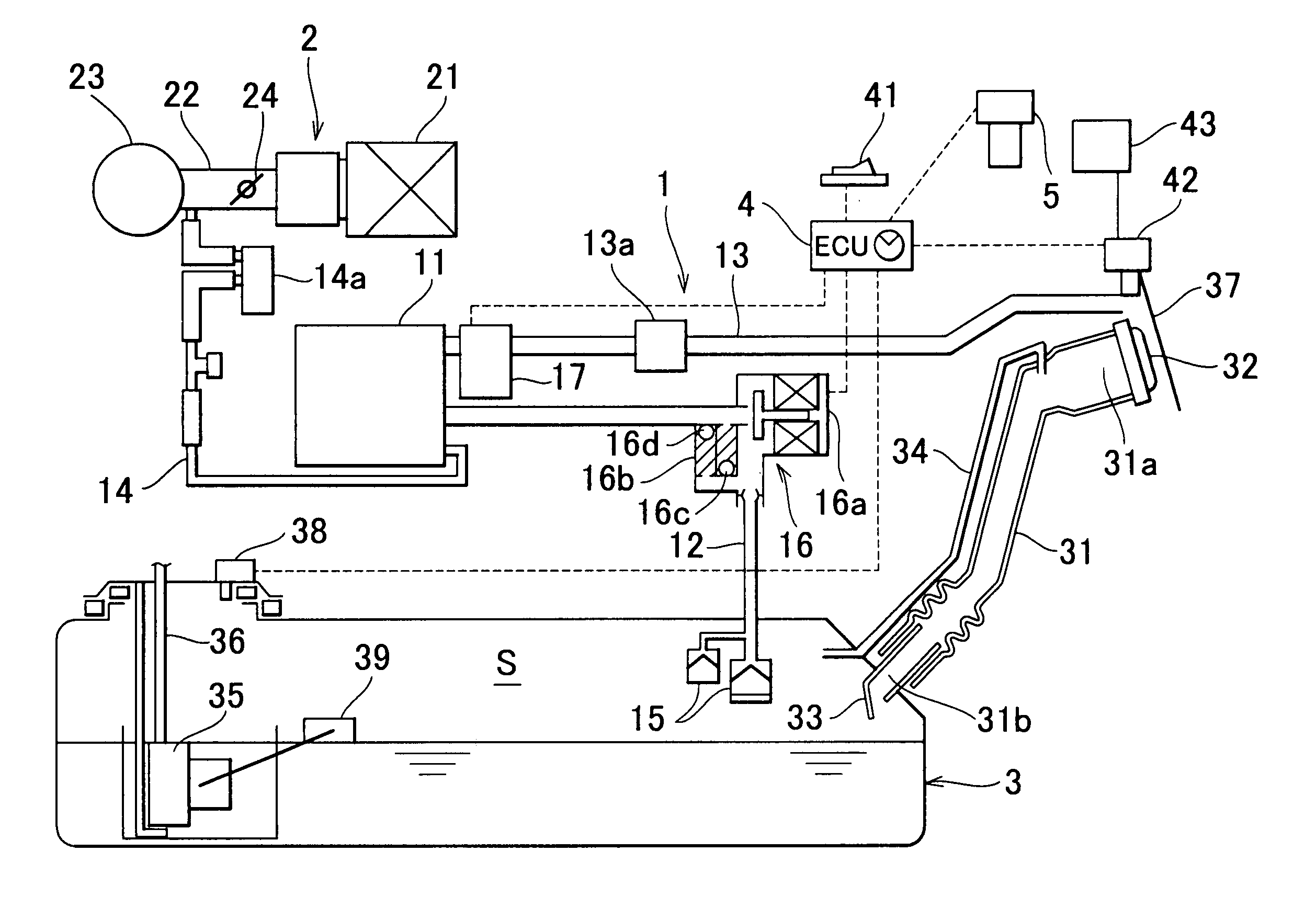
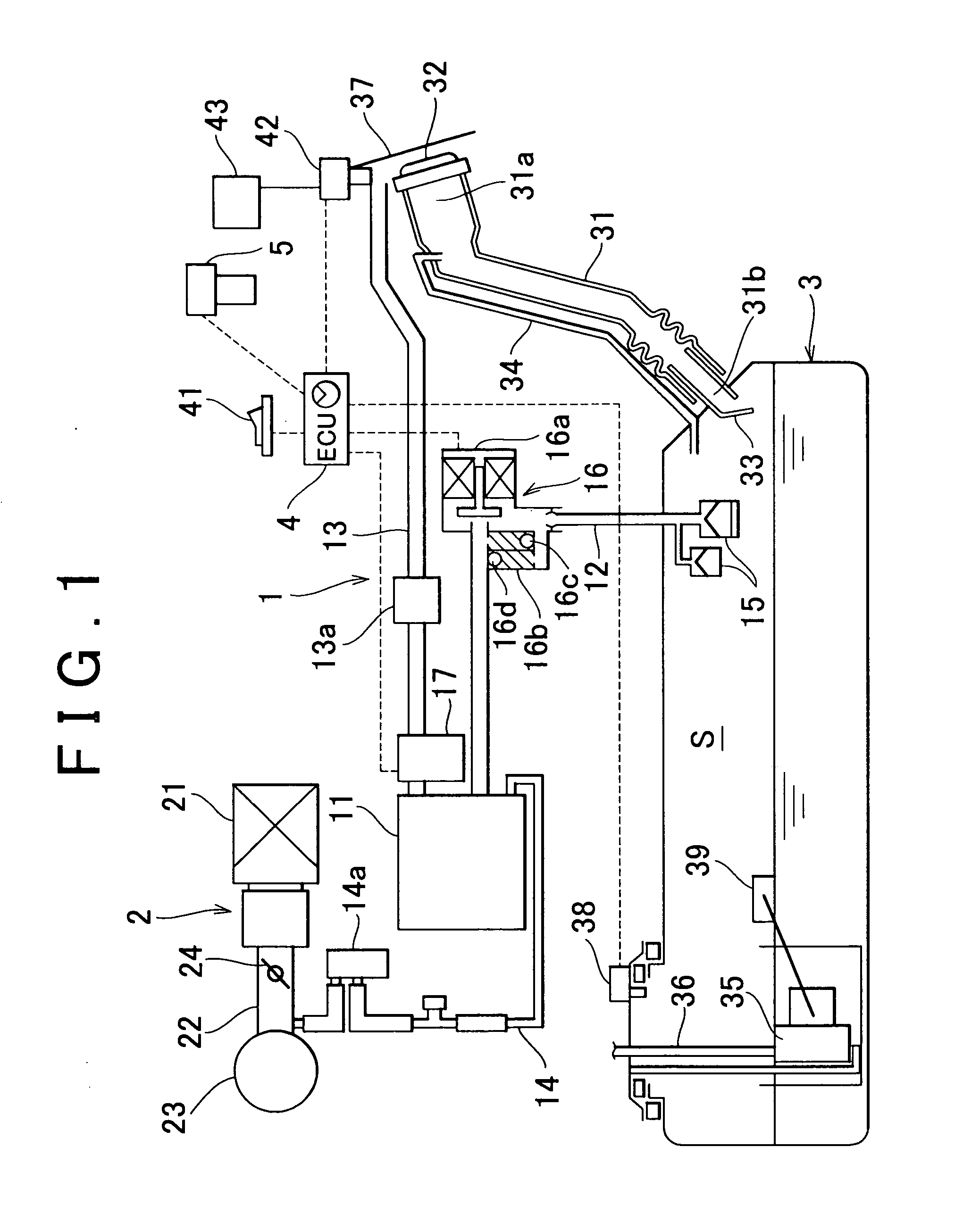
[0029]FIG. 1 schematically shows a structure of a canister system 1 according to the embodiment and an intake system 2 of the engine to which the canister system 1 is connected.

Structure of Intake System 2 and Fuel Tank 3

[0030] Referring to FIG. 1, an intake system 2 of an engine (internal combustion engine) is provided with an air cleaner 21, an intake pipe 22, a surge tank 23, and a not-shown intake manifold in the order from the upstream side in the direction of the intake air flow. A throttle valve 24 is provided within the intake pipe 22. The intake manifold is provided with a not-shown fuel injection valve (injector).

[0031] A fuel tank 3 that stores a fuel to be supplied to the injector is formed of, for example, a synthetic resin material, to which a feed ...


PUM


Abstract

In a canister system of seal type, a purge VSV is closed even if a predetermined purge condition is established so as to prevent direct purging of an evaporated fuel within a fuel tank into an intake system of an engine when one of the following conditions is established, that is, (1) a motor pump of an OBD pump module is driven; (2) a switching valve of the OBD pump module is set to ON; and (3) a closing valve is opened.

Description

INCORPORATION BY REFERENCE [0001] The disclosure of Japanese Patent Application No. 2004-309313 filed on Oct. 21, 2004 including the specification, drawings and abstract is incorporated herein by reference in its entirety. BACKGROUND OF THE INVENTION [0002] 1. Field of the invention [0003] The invention relates to an evaporated fuel treatment device and an evaporated fuel treatment method for treating an evaporated fuel generated within a fuel tank (for example, a fuel tank for a vehicle) without discharging the evaporated fuel to the atmosphere. More specifically, the invention relates to elimination of the failure resulting from direct introduction of the evaporated fuel within the fuel tank into an intake system of an internal combustion engine. [0004] 2. Description of the Related Art [0005] A canister system (evaporated fuel treatment device) for preventing discharge of the evaporated fuel generated within the fuel tank into the atmosphere is well known as being provided for th...

Claims


Application Information

Patent Timeline
Patent Type & Authority Applications(United States)
IPC IPC(8): G01M19/00F02M25/08G01M99/00
CPCF02M25/0809F02M25/0818F02M25/0854F02M25/089
Inventor SUZUKI, NAOTO
Owner TOYOTA JIDOSHA KK
Why Eureka
Try Eureka