Timing generator and test device

a timing generator and test device technology, applied in the field of timing generators, can solve the problems of jitter in the clock to be generated, calorific value in the delaying circuit, and inadmissible jitter in the high precision lsi, and achieve the effect of less jitter

Inactive Publication Date: 2006-04-27
ADVANTEST CORP
View PDF11 Cites 2 Cited by
  • Summary
  • Abstract
  • Description
  • Claims
  • Application Information

AI Technical Summary

Benefits of technology

[0014] The delaying circuit section may have a plurality of cascade-connected delay elements, the delay control section may have a plurality of delay setting flip-flops provided corresponding to the plurality of delay elements and each of the delay setting flip-flops may incorporate the delay setting data corresponding to pulse outputted out of corresponding delay element and may control the value of delay of the corresponding delay element based on the incorporated delay setting data.
[0021] According to the invention, the timing signal having a desirable pattern may be generated with less jitter.

Problems solved by technology

However, such circuit causes a problem that a number of pulses and pattern of pulses passing through the delaying circuit vary corresponding to the pattern of the pulses selected by the logical gate and that a calorific value in the delaying circuit varies as a result.
Due to that, a value of delay in the delaying circuit fluctuates, causing jitter in the clock to be generated.
Such jitter is not permissible in the high precision LSI and the like.
Still more, while it is necessary to provide the delaying circuit for generating the clock in the vicinity of the dummy delaying circuit to keep the temperature of the delaying circuit for generating the clock constant, there is also a problem that a signal in the dummy delaying circuit interferes with a signal in the delaying circuit for generating the clock, causing jitter in the clock to be generated.
For example, phase of the pulses passing through the delaying circuit for generating the clock becomes almost identical with phase of the pulses passing through the dummy delaying circuit and causes interference depending on setting of the value of delay in the delaying circuit for generating the clock.

Method used


Image

  • Timing generator and test device
  • Timing generator and test device
  • Timing generator and test device

Examples


Embodiment Construction

[0026] The invention will now be described based on preferred embodiments, which do not intend to limit the scope of the invention, but exemplify the invention. All of the features and the combinations thereof described in the embodiments are not necessarily essential to the invention.

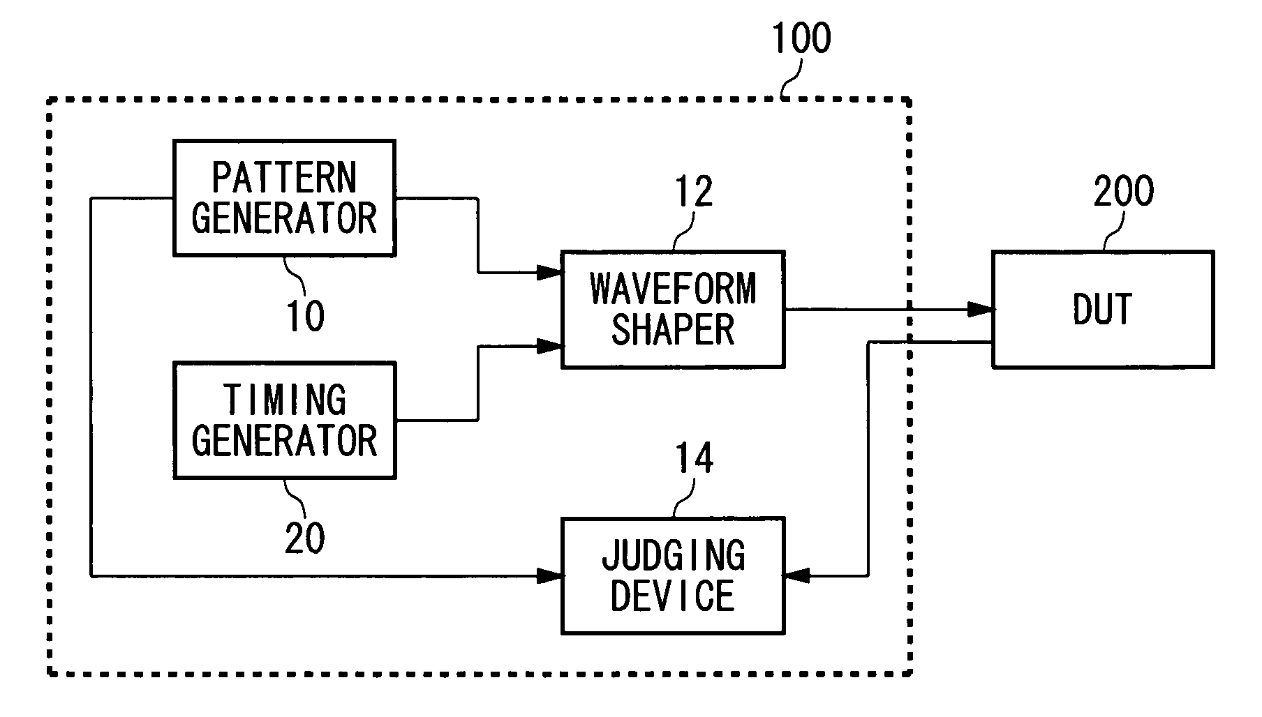
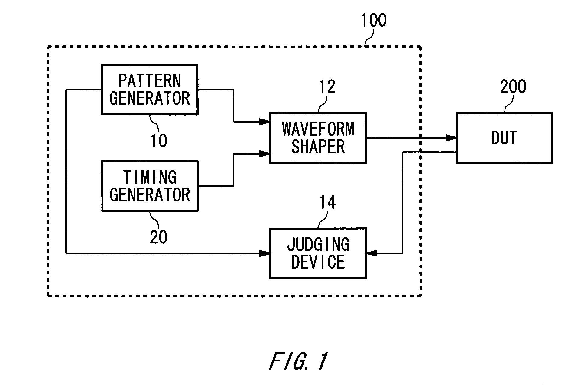
[0027]FIG. 1 is a diagram showing one exemplary configuration of a test apparatus 100 according to an embodiment of the invention. The test apparatus 100 is an apparatus for testing an electronic device 200 such as a semiconductor circuit and includes a pattern generator 10, a waveform shaper 12, a judging device 14 and a timing generator 20.

[0028] The pattern generator 10 generates a test pattern for testing the electronic device 200. The test pattern is a digital signal represented by a pattern of 1 / 0 for example. The waveform shaper 12 generates an input signal to be inputted to the electronic device 200 based on the test pattern. For example, the waveform shaper 12 generates the input signal havi...


PUM


Abstract

There is provided a timing generator for generating a timing signal based on a given reference clock, having a delaying circuit section for outputting each pulse of the reference clock by delaying by a value of delay given per each of the pulse and a pulse selecting and outputting section for passing and outputting only pulses to be outputted as the timing signal among the pulses outputted out of the delaying circuit section.

Description

REFERENCE TO RELATED APPLICATION [0001] This is a continuation application of PCT / JP2005 / 018709 filed on Oct. 11, 2005 which claims priority from a Japanese Patent Application No. JP2004-299321 filed on Oct. 13, 2004, the contents of which are incorporated herein by reference.BACKGROUND OF THE INVENTION [0002] 1. Technical Field [0003] The present invention relates to a timing generator for generating a timing signal based on a given reference clock and to a test apparatus having the timing generator. More specifically, the invention relates to a timing generator whose calorific value is stabilized. [0004] 2. Related Art [0005] Operating speed of electronic devices such as LSI is improving lately. With that, it has become necessary to generate a high precision clock in a test apparatus and the like for testing such electronic devices. Conventionally, in order to generate a clock having a desirable pattern, there has been known a circuit having a logic gate that passes desirable puls...

Claims


Application Information

Patent Timeline
Patent Type & Authority Applications(United States)
IPC IPC(8): G01R13/02
CPCG01R31/31922
Inventor NEGISHI, TOSHIYUKISATO, NAOKI
Owner ADVANTEST CORP
Why Eureka
Try Eureka