Illuminating textile device

a textile and illumination technology, applied in the field of illumination textile devices, can solve the problems of limited illumination area, low illumination intensity of passive reflective illumination devices, and inability to use active illumination devices with large illumination areas, etc., to achieve increased illumination area, enhanced illumination intensity, and sustained lifetime

Inactive Publication Date: 2006-04-27
BAYCOM OPTO ELECTRONICS TECH
View PDF2 Cites 32 Cited by
  • Summary
  • Abstract
  • Description
  • Claims
  • Application Information

AI Technical Summary

Benefits of technology

[0007] It is therefore an objective of the present invention to provide an illuminating textile device with enhanced illumination intensity, sustained lifetime, and increased illumination area.

Problems solved by technology

If the light intensity of other external light sources is insufficient, the illumination intensity of the passive reflective illuminating devices also diminishes.
However, for the active illuminating devices, the illumination area is often limited to a small portion of the active illuminating device.
An active illumination device with large illumination area is often unavailable and difficult to manufacture.

Method used


Image

  • Illuminating textile device
  • Illuminating textile device
  • Illuminating textile device

Examples


Embodiment Construction

[0020] Reference will now be made in detail to the present preferred embodiments of the invention, examples of which are illustrated in the accompanying drawings. Wherever possible, the same reference numbers are used in the drawings and the description to refer to the same or like parts.

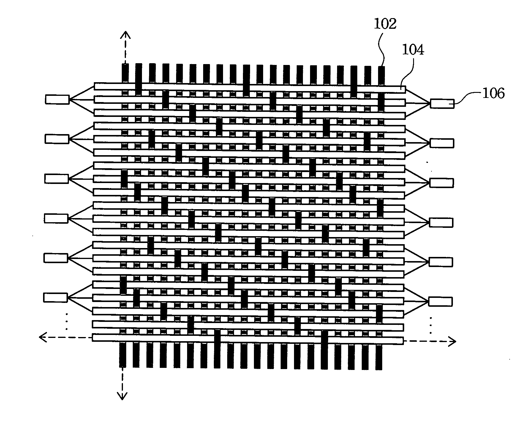
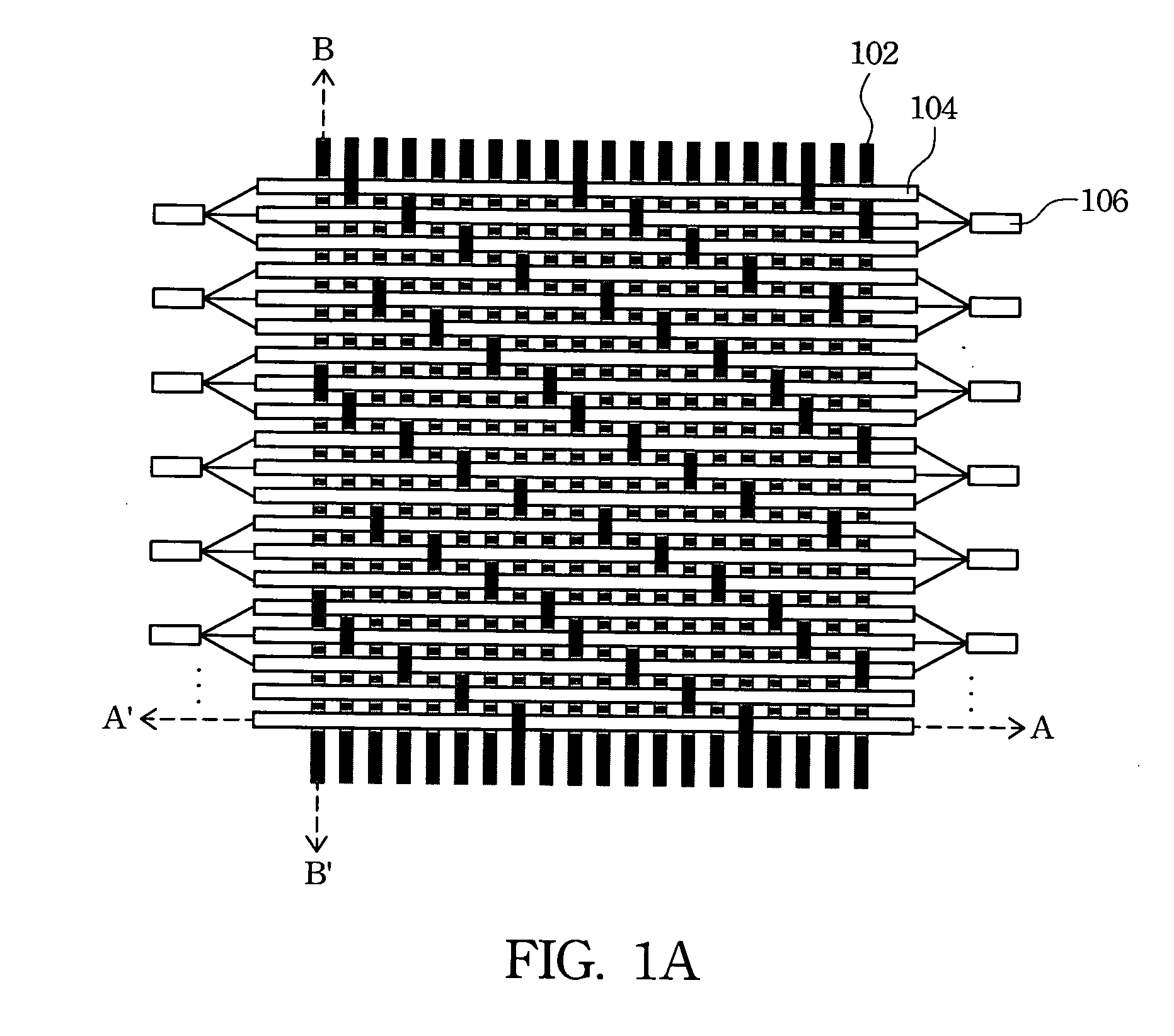
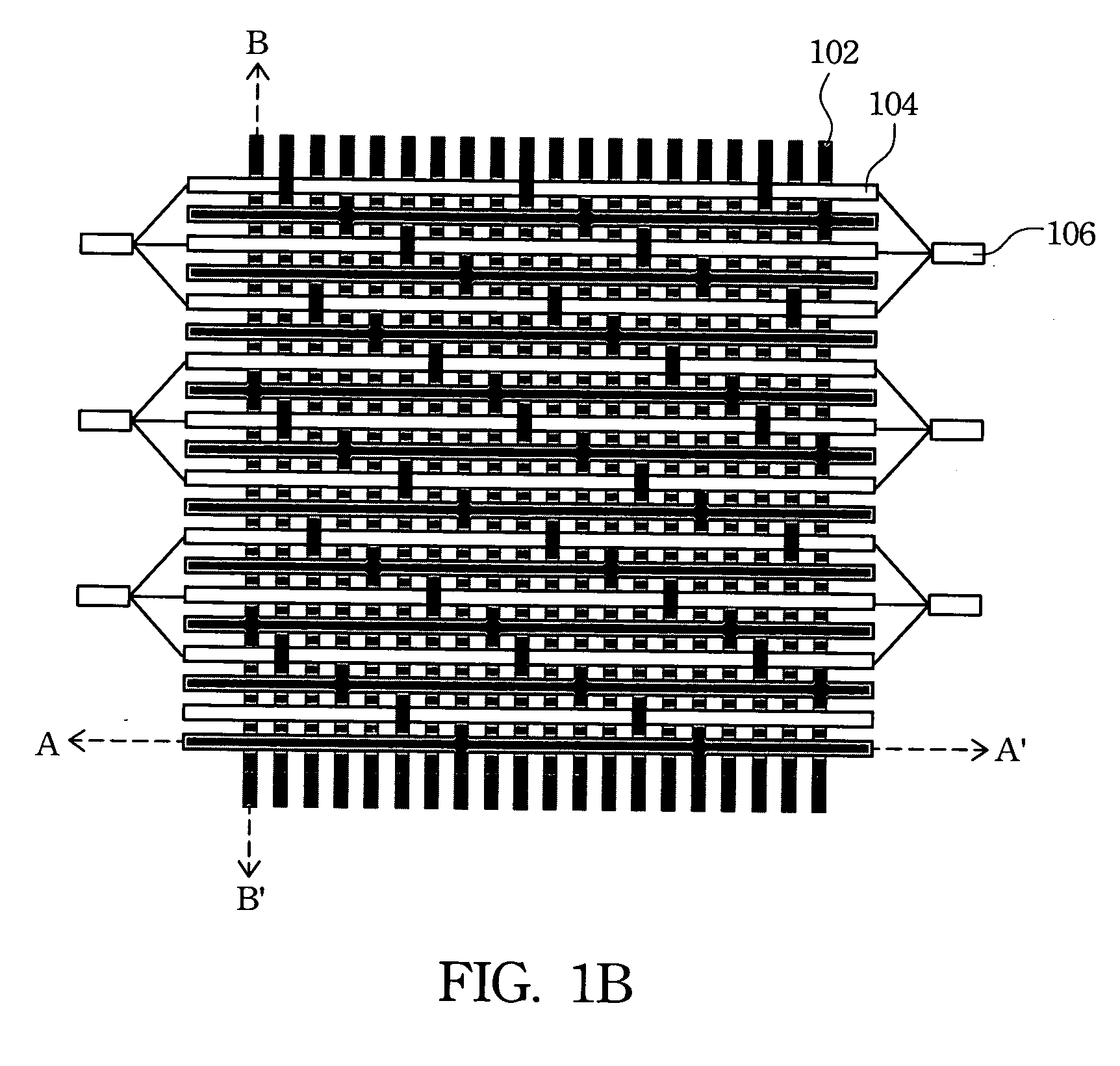
[0021] The present invention provides an active illuminating textile device utilizing an optical fabric layer as a light source. Compared with the conventional active illuminating devices, the illuminating textile device according to the present invention has the advantages of a longer lifetime, lower power consumption, decreased volume, and increased illumination area. The illumination textile device according to the present invention can be employed in clothes, vests, or raincoats. The illuminating textile device according to the present invention can also be applied for entertainment in devices such as decorations, toys, kites or dolls.

[0022] The illuminating textile device according to the pre...


PUM

PropertyMeasurementUnit
transparentaaaaaaaaaa
light intensityaaaaaaaaaa
areaaaaaaaaaaa

Abstract

The present invention relates to an illuminating textile device. The illuminating textile device has a pattern layer and an optical fabric layer. The pattern layer has a transparent area and a non-transparent area. The optical fabric layer is woven from fiber optics and threads for providing the light source. The optical fabric layer is attached to the pattern layer by sewing or a fixation component.

Description

RELATED APPLICATIONS [0001] The present application is based on, and claims priority from, Taiwan Application Serial Number 93132228, filed Oct. 22, 2004, the disclosure of which is hereby incorporated by reference herein in its entirety. BACKGROUND [0002] 1. Field of Invention [0003] The present invention relates to an illuminating textile device. More particularly, the present invention relates to an illuminating textile device utilizing an optical fabric layer as a light source. [0004] 2. Description of Related Art [0005] Conventionally, illuminating devices can be classified into two categories. One type is a passive reflective illuminating device, which illuminates by reflecting light from other external light sources. Light from the external light sources is reflected by reflective material coated on the passive reflective illuminating device. However, for the passive reflective illuminating devices, the illumination intensity is mainly determined by the light of other externa...

Claims


Application Information

Patent Timeline
Patent Type & Authority Applications(United States)
IPC IPC(8): F21V21/08
CPCD03D15/00D03D15/0033D10B2401/20D10B2501/00F21V2200/15D10B2505/18G02B6/001G09F21/02D10B2501/042D03D15/54D03D15/547
Inventor PENG, CHI-TSUNGWANG, CHIEN-TANG
Owner BAYCOM OPTO ELECTRONICS TECH
Why Eureka
Try Eureka