Speaker device

Active Publication Date: 2006-04-27
SONY CORP
View PDF10 Cites 44 Cited by
  • Summary
  • Abstract
  • Description
  • Claims
  • Application Information

AI Technical Summary

Benefits of technology

[0017] According to a loudspeaker device, which is compact and capable of reproduction up to high range, of the present invention, a reinforcement ring is fixed to a flat portion or to the flat portion including the vicinity thereof, where a domed diaphragm in the center and an edge-like diaphragm of a diaphragm used for an dynamic loudspeaker and an dynamic electromagnetic induction loudspeaker are joined; and an end surface of a voice coil bobbin or an end surface of a conductive 1-turn ring is stuck to the flat portion of the acoustic diaphragm or of the reinforcement ring to increase the mechanical strength of a flat portion.
[0018] According to the lou

Problems solved by technology

Particularly, if the dip is in the audible band, there is an inconvenience in which the quality of acoustic signals deteriorates.
Thus, a problem in which the necessary acoustic pressure cannot be

Method used


Image

  • Speaker device
  • Speaker device
  • Speaker device

Examples


Example

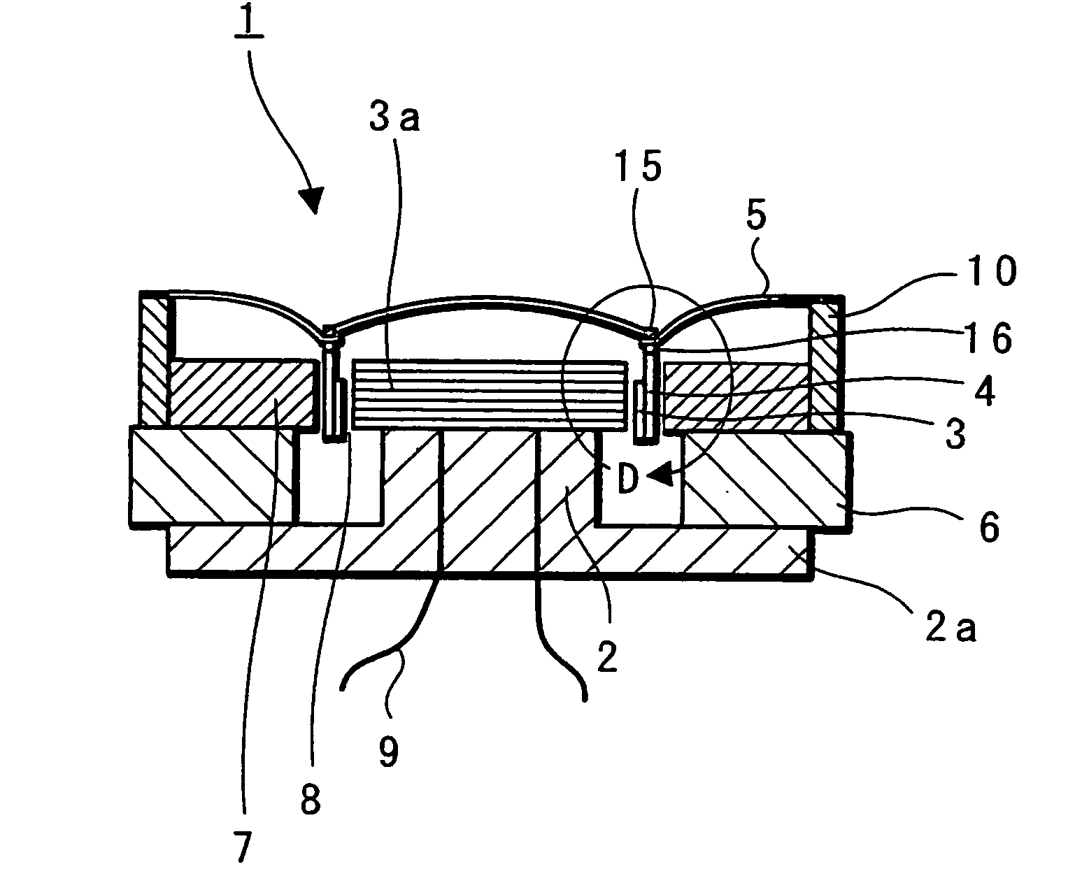
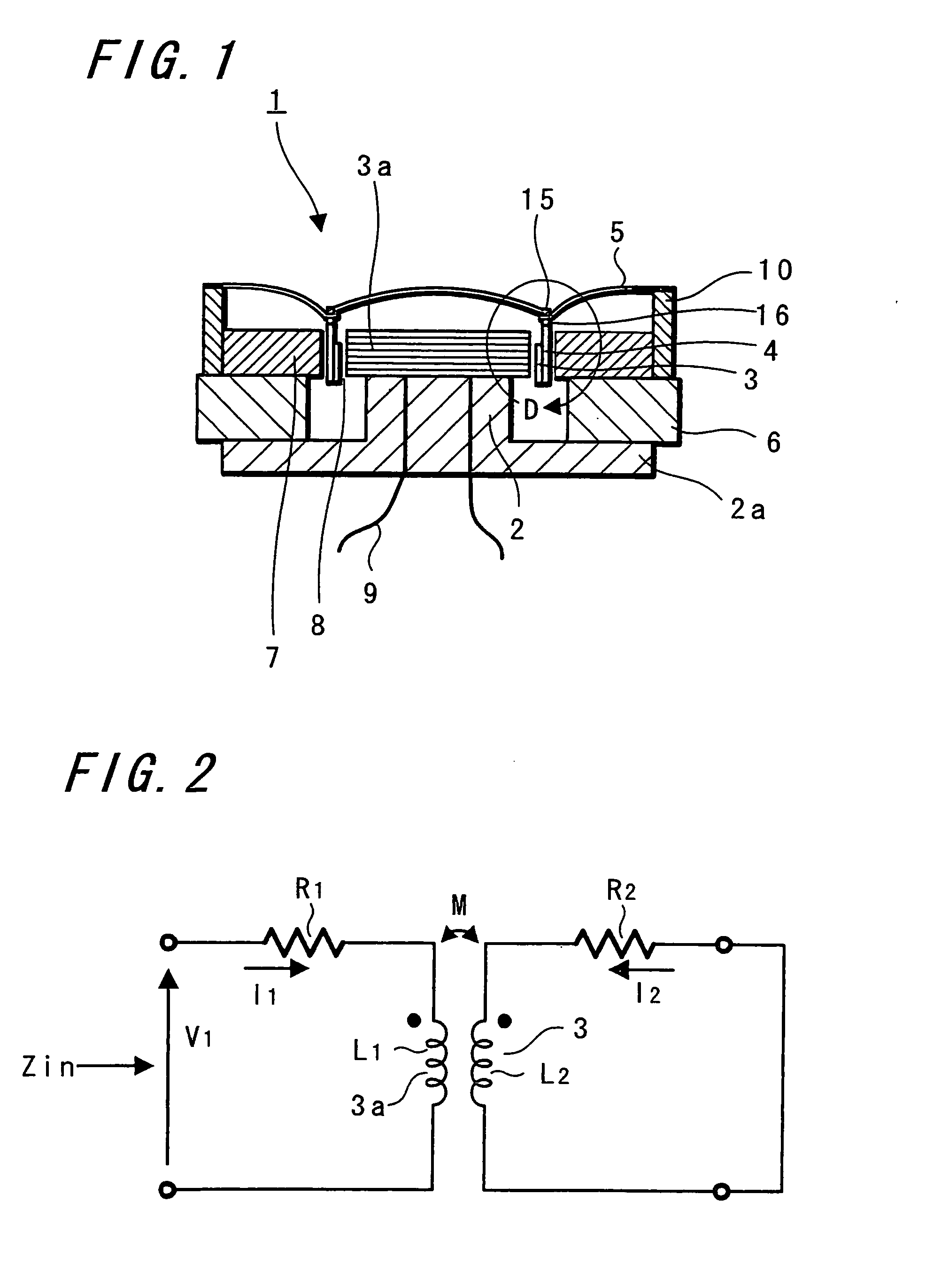
[0034] Hereinafter, each embodiment of a loudspeaker device of the present invention is explained referring to drawings. FIG. 1 is a sectional side view in which the present invention is applied to a dynamic electromagnetic induction loudspeaker, and FIG. 2 shows an equivalent circuit of the dynamic electromagnetic induction loudspeaker shown in FIG. 1.

[0035] In FIG. 1, a loudspeaker device 1 includes a frame portion, an acoustic diaphragm and a driving means.

[0036] As regards the frame, a columnar pole piece 2 whose diameter is smaller than that of a lower surface plate is integrally formed with a lower surface plate 2a formed of a disk-like metal and is erected approximately in the center of the lower surface plate 2a, and a concentric magnet 6 is joined to the lower surface plate 2a to surround the outer circumference of the pole piece 2.

[0037] Further, a disk-like metal upper surface plate 7 concentrically formed is joined onto the magnet 6. The frame portion is constructed b...


PUM


Abstract

A loudspeaker device 1 includes an acoustic diaphragm 5 composed of a domed diaphragm 11, an edge-like diaphragm 13, and a junctional flat portion 12 which joins those domed and edge-like diaphragms, and a joined portion 23 where an end surface of a bobbin 4 of a voice coil or of a conductive 1-turn ring 3 is stuck and fixed to the junctional flat portion 12 or a reinforcement ring 15; and the reinforcement ring 15 is stuck and fixed to the junctional flat portion 12 from above or from under, thereby increasing the mechanical strength of the junctional flat portion 12 of the acoustic diaphragm 5. A loudspeaker device in which unnecessary vibrations are removed and also the quality of acoustic signals is excellent up to high range is provided.

Description

TECHNICAL FIELD [0001] The present invention relates to a loudspeaker device used for audio equipment, video equipment, or various pieces of other equipment, and particularly to a loudspeaker device in which the strength of a junctional flat portion of an acoustic diaphragm is increased. BACKGROUND ART [0002] As shown, for example, in FIG. 12, an acoustic diaphragm in a conventional loudspeaker device has a domed diaphragm 121 shaped like a dome in the center, and an edge-like diaphragm 129 which is integrally formed with the domed diaphragm 121 and extending from the circular periphery of the domed diaphragm 121 using a polymer film, metal or the like, such that the edge-like diaphragm 129 has a predetermined curvature of concavity or convexity or is linear in cross section. [0003] A voice bobbin 122 on which a voice coil 123 is wound is joined to a junctional portion where the domed diaphragm 121 and edge-like diaphragm 129 of an acoustic diaphragm 120 are integrated such that the...

Claims


Application Information

Patent Timeline
IPC IPC(8): H04R1/00H04R9/06H04R11/02H04R7/12H04R7/16H04R7/18H04R9/02H04R9/04
CPCH04R7/16H04R9/06H04R9/04H04R7/18H04R7/12
Inventor OHASHI, YOSHIOURYU, MASARUTSUNODA, NAOTAKAHARA, TAKESHI
Owner SONY CORP
Why Eureka
Try Eureka