Image processing apparatus, image pickup device and program therefor

a technology of image processing and image pickup, which is applied in the direction of electrical devices, instruments, computing, etc., can solve the problems of user input and user extreme cumbersome tasks, and achieve the effects of reducing the burden on the user to input various parameters regarding the 3d image transformation process, reducing the burden on the user for indication, and maintaining the quality of the 3d vision imag

Inactive Publication Date: 2006-04-27
MERCURY SYSTEM CO LTD
View PDF19 Cites 51 Cited by
  • Summary
  • Abstract
  • Description
  • Claims
  • Application Information

AI Technical Summary

Benefits of technology

[0010] According to this construction, the 3D transformation parameter is specified based on the image pickup condition captured by the image pickup device. Thus, there is no need for the user to indicate the 3D transformation parameter. Therefore, the burden on the user to input various parameters regarding the 3D image transformation process is reduced. Further, if the environment (such as brightness in the surrounding space) at the time of an image pickup is well suited to the image pickup conditions, a 3D vision image of an accurate reproduction of the image of the original object is obtained by using the 3D transformation parameters specified based on the image pickup conditions.
[0011] In the image processing apparatus having the above first or second feature, the 3D transformation parameter may be added to either the head or the bottom portion of original image data, or the 3D transformation parameter and original image data may be stored separately while storing a table correlating the information for identifying original image data and the 3D transformation parameter in the storage device. In the image processing apparatus having the above first or second feature, the 3D transformation unit may comprise a calculation unit for obtaining a depth value for each pixel from the original image data; an adjusting unit for adjusting the depth value obtained by the calculation unit; and an image generating unit for generating the right eye image and the l

Problems solved by technology

However, when such a construction to be applied to the above technology, it is necessary for the user to indicate the parameter(s) in each 3D transformation process with regard to a plane image, which is a cumbersome task for the user to perform.
Especiall

Method used


Image

  • Image processing apparatus, image pickup device and program therefor
  • Image processing apparatus, image pickup device and program therefor
  • Image processing apparatus, image pickup device and program therefor

Examples


first embodiment

A: FIRST EMBODIMENT

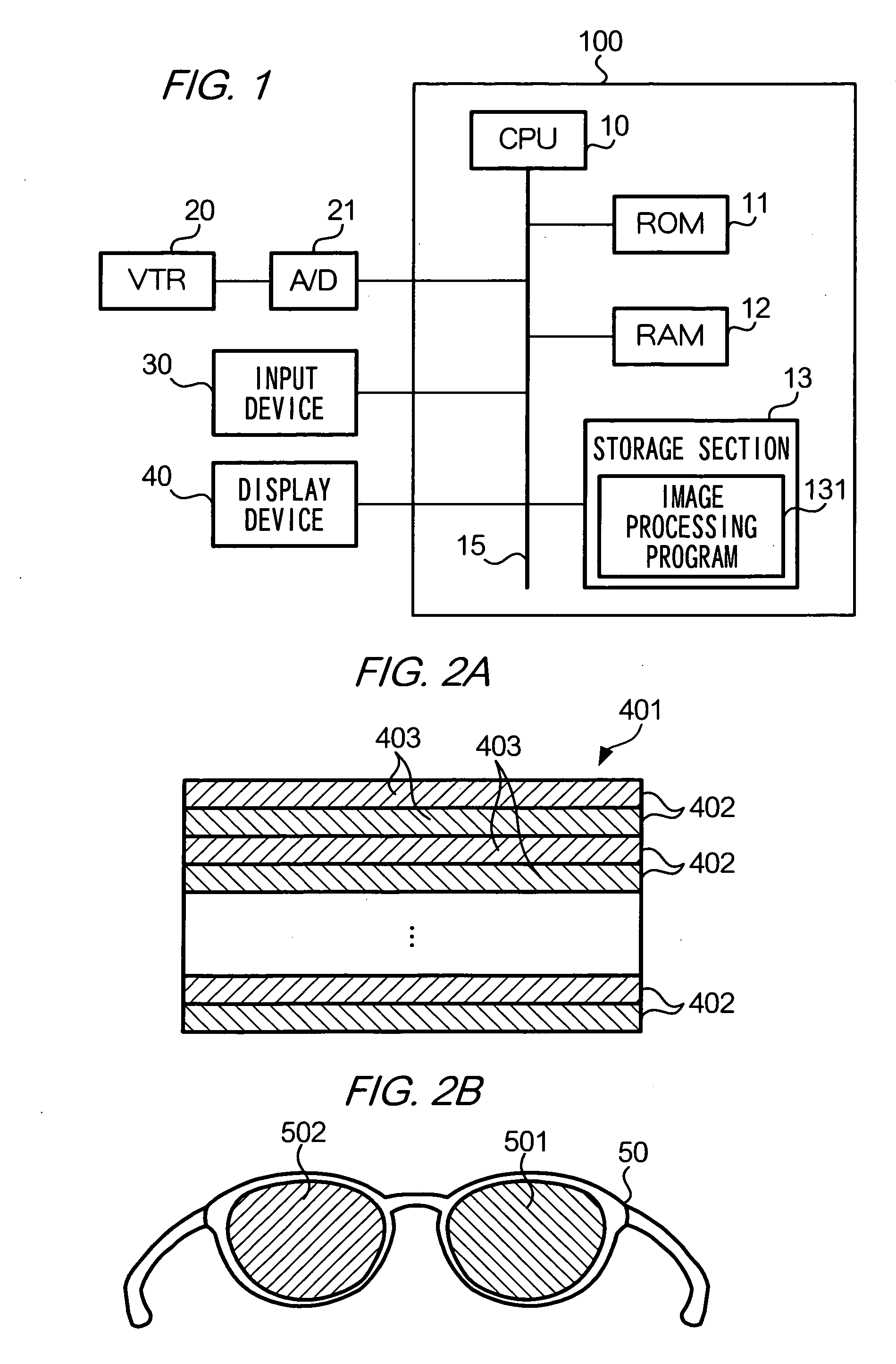
[0036]FIG. 1 is a block diagram illustrating the construction of an image processing apparatus according to a first embodiment of the present invention. As shown in the figure, image processing apparatus 100 comprises: CPU (Central Processing Unit) 10; ROM (Read Only Memory) 11; RAM (Random Access Memory) 12; and storage device 13 which are connected to CPU 10 through bus 15. Display device 40 and input device 30 are also connected to bus 15. As described above, image processing apparatus 100 has a similar structure to that of a commonly used computer as typified by a personal computer.

[0037] CPU 10 is for centrally controlling each portion of image processing apparatus 100 to realize various functions by executing calculations and control of the portions according to a program. ROM 11 is a memory for storing a program run by CPU 10, and RAM 12 is a memory providing a work area for CPU 10.

[0038] Storage device 13 is a device for storing various programs run by C...

second embodiment

B: SECOND EMBODIMENT

[0073] In the above-described first embodiment, the 3D transformation process is executed by using a 3D transformation parameter selected by the user. In the present embodiment, on the other hand, the 3D transformation parameters are specified based on information obtained through an image pickup device such as a camera. In the following description, the technical components of the present embodiment having the same role as the first embodiment will be depicted with the same numerals and the description will accordingly be omitted.

[0074]FIG. 11 shows a block diagram illustrating image processing apparatus 100 according to the present embodiment. As shown in the figure, bus 15 of image processing apparatus 100 is connected to image pickup device 70 through an interface (not shown). Image pickup device 70 is for picking up a stationary image or moving images, and is comprised of, for example, a digital camera. Image pickup device 70 comprises image pickup element ...

modified embodiment 1

C-1: MODIFIED EMBODIMENT 1

[0087] While in the above-described embodiments the 3D transformation parameters are added to original image data, the method of storing the 3D transformation parameters is not limited to this. For example, as shown in FIG. 14, 3D transformation parameters and original image data are stored in separate files in storage device 13 together with a table describing the relationship between original image data and 3D transformation parameters. The table shown in FIG. 14 correlates information for identifying the original image data and information for identifying a 3D transformation parameter to be used for executing a 3D transformation process of original image data. CPU 10 may read out the correlated 3D transformation parameter of original image data from the table when CPU 10 executes a 3D transformation process of the original image data, and use it in the 3D transformation process.

[0088] In another construction, as shown in FIG. 15, 3D transformation param...


PUM


Abstract

CPU 10 generates from original image data representing an image, a right eye image and a left eye image mutually having a parallax. CPU 10 also specifies the 3D transformation parameter depending on the indication by a user, and stores the specified 3D transformation parameter in storage device 13 in association with original image data.

Description

BACKGROUND OF THE INVENTION [0001] 1. Field of the Invention [0002] The present invention relates to a technology for making from a plane image an image which can be perceived by a user as a 3D (three-dimensional) object. [0003] 2. Description of the Related Art [0004] By providing two images having a mutual parallax, and making a user view one image with his / her left eye and the other with the right eye, the image can be perceived as a 3D image by the user. A process for making such images having a mutual parallax (which is called “3D vision image set” hereafter) from a plane image is proposed, for example, in Japanese Laid-open Patent Publication 2002-123842. In the technology, the 3D vision image set is produced by using various parameters such as depth of an image to be perceived by the user who views the images. [0005] It would be convenient, when using the above technology, if the user could select his / her preferable values of those various parameters to be used for producing ...

Claims


Application Information

Patent Timeline
IPC IPC(8): G06K9/00H04N13/128
CPCH04N13/0018H04N13/0022H04N13/0051H04N13/026H04N13/0278H04N13/0434H04N13/337H04N13/167H04N13/279H04N13/122H04N13/128H04N13/261
Inventor ERA
Owner MERCURY SYSTEM CO LTD
Why Eureka
Try Eureka