Power generation and supply system

a power generation and supply system technology, applied in the direction of electrochemical generators, reactant parameter control, hybrid cells, etc., can solve the problems of increasing electricity cost, inability to keep up with demand, and number of power outages

Inactive Publication Date: 2006-04-27
ENERGY CONVERSION DEVICES INC
View PDF4 Cites 59 Cited by
  • Summary
  • Abstract
  • Description
  • Claims
  • Application Information

AI Technical Summary

Benefits of technology

[0008] The present invention discloses a power generation and supply system comprising one or more solar cells, a rechargeable battery, an electrolyzer, a hydrogen distribution system, and an electricity distribution system in electrical communication with the one or more solar cells and / or the rechargeable battery.
[0009] The one or more solar cells may comprise one or more triple junction amorphous silicon solar cells. The one or more solar cells may also comprise one or more roofing shingles including a solar cell active material deposited on a substrate. Electricity produced by the one or more solar cells is supplied to a battery for storage and / or the electricity distribution system for distribution to a power grid and / or one or more electrical devices. While various rechargeable batteries may be utilized, preferably, the rechargeable battery is a nickel metal hydride battery.
[0010] The electrolyzer receives electricity from the one or more solar cells and / or the rechargeable battery and produces hydrogen via the electrolytic decomposition of water. Hydrogen produced by the electrolyzer is then transfered to the hydrogen distribution system. The hydrogen distribution system receives the hydrogen produced from the electrolyzer and supplies the hydrogen to a hydrogen powered vehicle, a hydrogen consuming device, or a hydrogen storage vessel.
[0011] The hydrogen distribution system may comprise a hydrogen storage system in gaseous communication with the electrolyzer for receiving hydrogen produced by the electrolyzer and storing the received hydrogen in gaseous, liquid, or metal hydride form and a hydrogen dispenser for dispensing hydrogen from the hydrogen storage system to a hydrogen consuming device and / or a hydrogen storage vessel. The hydrogen storage system may comprise one or more pressure containment vessels at least partially filled with a hydrogen storage alloy.
[0012] The power generation and supply system according may further comprise a hydrogen fueled fuel cell in gaseous communication with the hydrogen distribution system and in electrical communication with the electricity distribution system and / or the rechargeable battery. The hydrogen fueled fuel cell receives hydrogen produced by the electrolyzer and produces electricity as needed to recharge the rechargeable battery and / or power one or more electrical devices. The hydrogen fueled fuel cell may be selected from alkaline fuel cells, PEM fuel cells, molten carbonate fuel cells, phosphoric acid fuel cells, and solid oxide fuel cells. The hydrogen fueled fuel cell may comprise one or more hydrogen electrodes including a hydrogen storage alloy providing for hydrogen storage capacity.

Problems solved by technology

The growing demand for electricity places a considerable strain on power grids worldwide resulting in numerous power outages.
The high demand for electricity in peak periods causes power plants to operate at a higher capacity during these periods, as power plants typically do not operate at full capacity to allow for generators to be taken offline for repairs and maintenance.
During peak periods, to keep up with demand, many power plants must utilize a greater percent of their generators, which can result in an inability to keep up with demand should one or more of the generators break down or require maintenance.
While electricity is produced from hydroelectric and nuclear power plants, these types of power plants are in limited supply and able to operate in limited locations, resulting in electricity typically being produced from generators fueled by fossil fuels.
The fossil fuels are also in limited supply, which will cause the cost of electricity to increase as the limited supply of fossil fuels is depleted.

Method used


Image

  • Power generation and supply system
  • Power generation and supply system
  • Power generation and supply system

Examples


Embodiment Construction

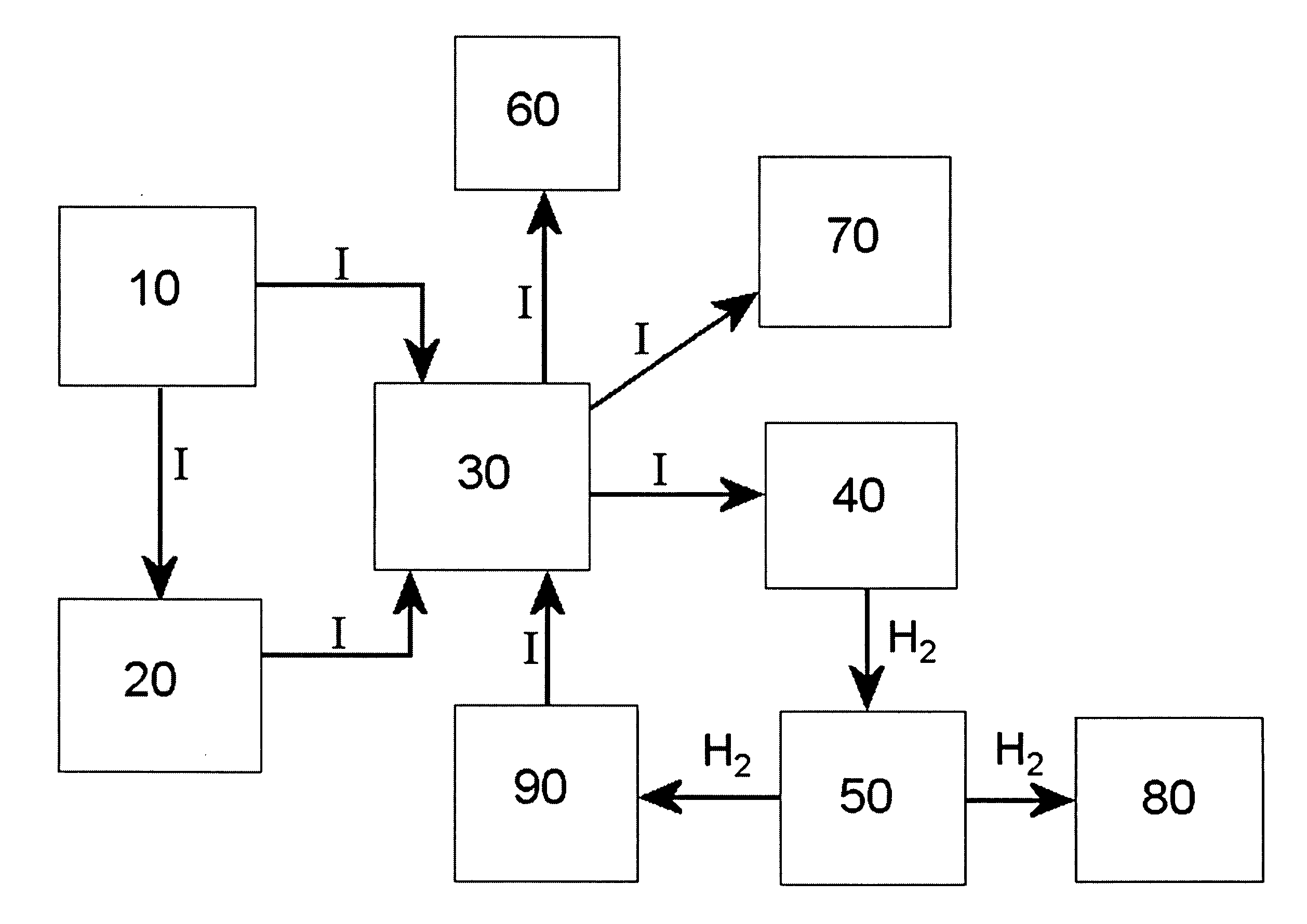
[0014] Disclosed herein, is a power generation and supply system which collects solar energy and converts the solar energy to electricity, which may be used to power one or more electrical devices and / or stored for later use. The electricity generated by the system may also be supplied from the system to a power grid and / or used to produce hydrogen via the electrolytic decomposition of water into hydrogen and oxygen. The hydrogen produced via electrolysis may be stored and used to fuel a hydrogen consuming device or fill a hydrogen storage vessel. The hydrogen consuming device may be a vehicle, generator, or device powered by a fuel cell or and / or a hydrogen internal combustion engine, or any other hydrogen consuming apparatus.

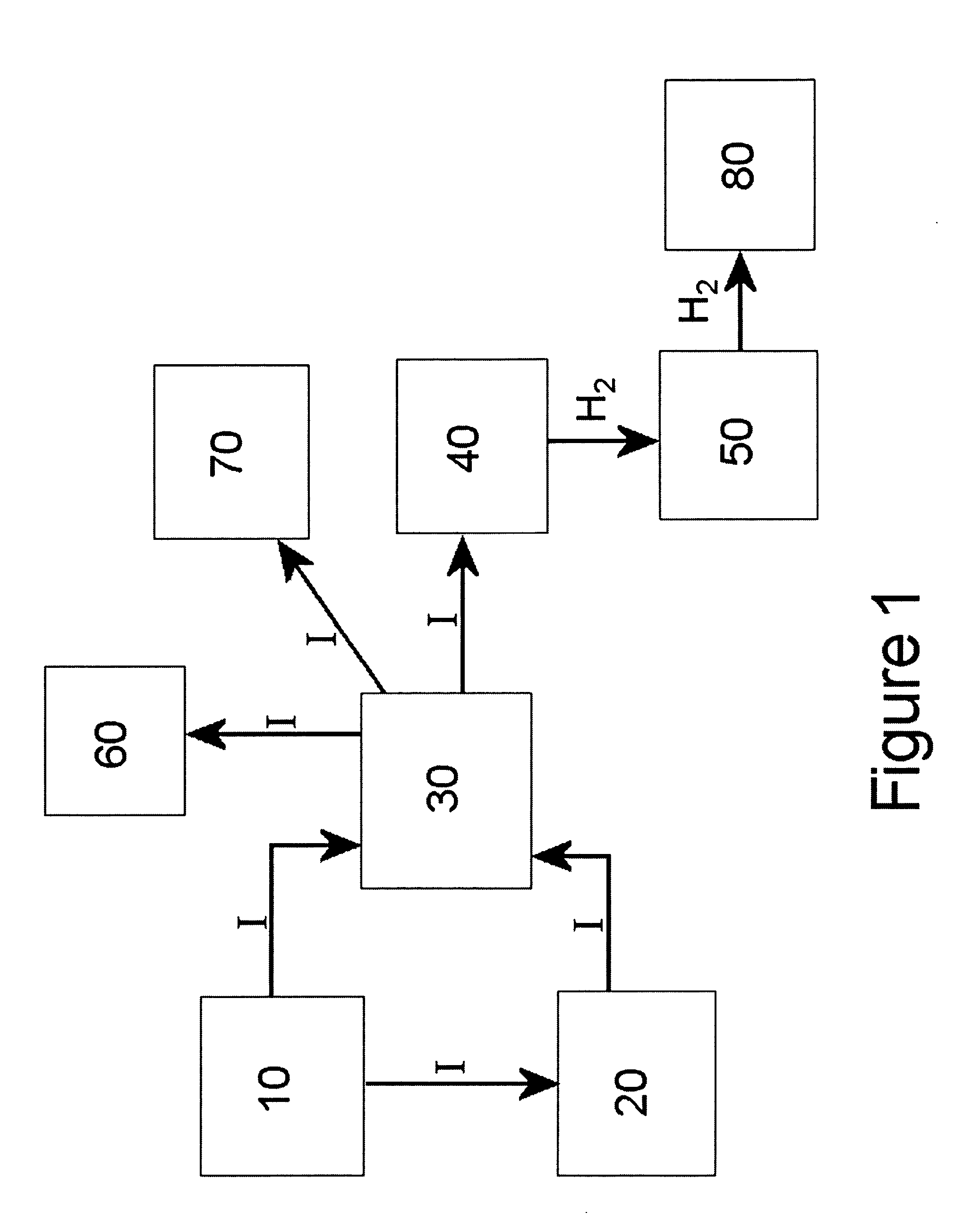
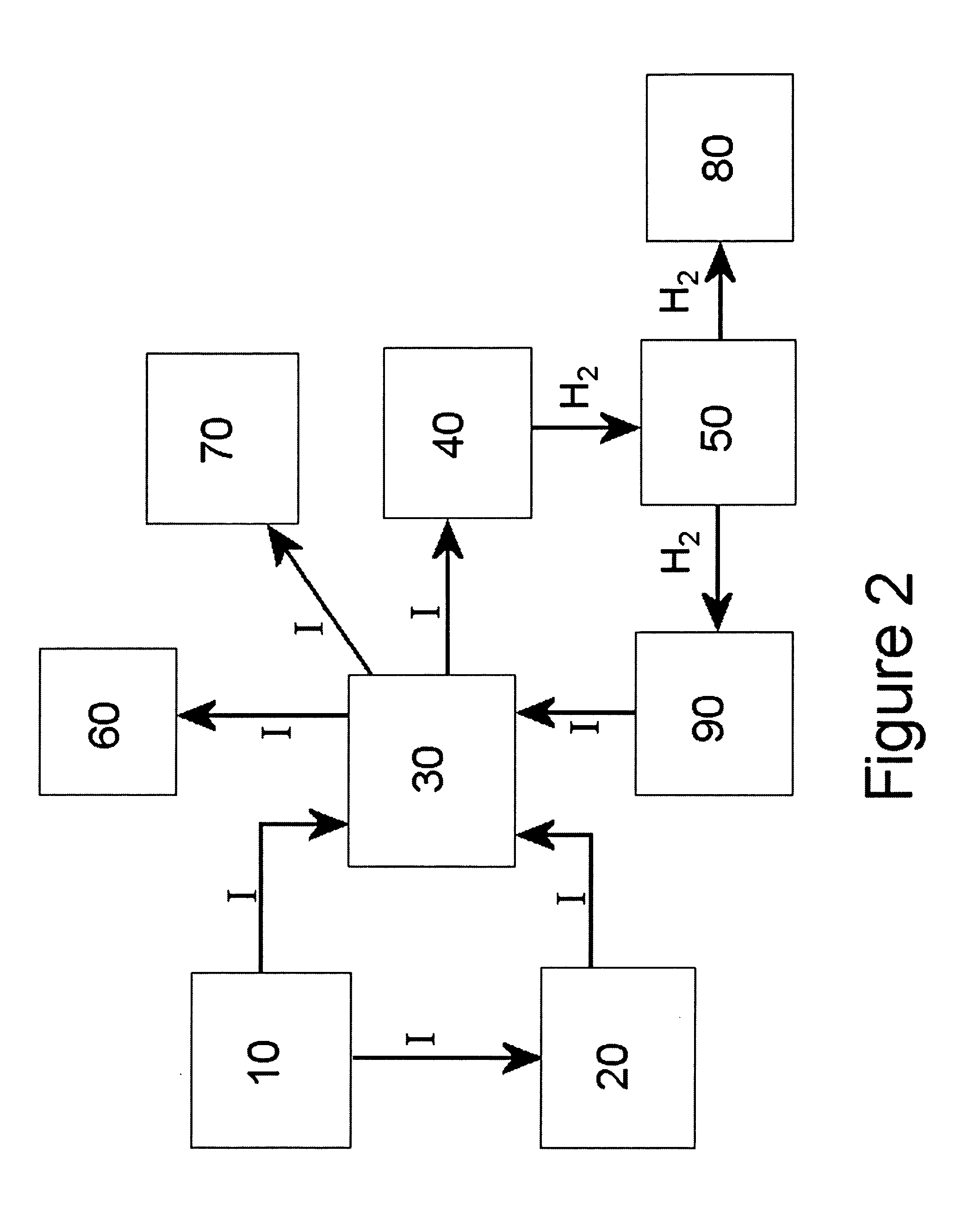
[0015] A schematic diagram of a first embodiment of the power generation and supply system is shown in FIG. 1. In FIG. 1, electrical current flows in the direction of the arrows and is designated as “I”, and hydrogen flows in the direction of the arrows and i...


PUM

PropertyMeasurementUnit
temperaturesaaaaaaaaaa

Abstract

A power generation and supply system utilizing one or more solar cells to produce electricity and hydrogen. The power generation and supply system includes an electrolyzer powered by the one or more solar cells for producing hydrogen, a hydrogen distribution system for distributing the hydrogen produced by the electrolyzer, a rechargeable battery for storing electricity produced by the solar cells, and an electricity distribution. The power generation and supply system according may further comprise a hydrogen fueled fuel cell which receives hydrogen produced by the electrolyzer and produces electricity as needed to recharge the rechargeable battery and/or power one or more electrical devices.

Description

FIELD OF THE INVENTION [0001] The present invention generally relates to a power generation and supply system utilizing a non-fossil fuel source of energy. More particularly, the present invention relates to a power supply and generation system utilizing solar energy to generate and supply electricity and hydrogen. BACKGROUND [0002] With the world's energy consumption increasing everyday, the demand for electricity and fossil fuels continues to increase worldwide. To date, fossil fuels, such as coal and petroleum, are the primary fuels for fueling power plants and vehicles. With the amounts of fossil fuels being in limited supply, alternative fuels and sources of energy have gained attention worldwide. [0003] The growing demand for electricity places a considerable strain on power grids worldwide resulting in numerous power outages. The high demand for electricity in peak periods causes power plants to operate at a higher capacity during these periods, as power plants typically do n...

Claims


Application Information

Patent Timeline
Patent Type & Authority Applications(United States)
IPC IPC(8): H01M12/00
CPCH01M8/04216H01M10/345H01M14/005H01M16/00H01M16/003Y02E60/50Y02E60/10
Inventor OVSHINSKY, STANFORD R.
Owner ENERGY CONVERSION DEVICES INC
Why Eureka
Try Eureka