Tube burner flame hole construction

a tube burner and flame hole technology, which is applied in the manufacture of burners, combustion types, burners, etc., can solve the problems of inconvenient construction, inconvenient use, and inability to meet the requirements of the burner, so as to improve simplify the process of the thin tube burner, and increase the mass density of the wall

Inactive Publication Date: 2006-04-27
GRAND HALL ENTERPRISE COMPANY +1
View PDF6 Cites 4 Cited by
  • Summary
  • Abstract
  • Description
  • Claims
  • Application Information

AI Technical Summary

Benefits of technology

[0006] The primary purpose of the present invention is to provide an improved construction of a thin burner wall that houses the flame hole to simplify the process of the thin tube burner. To achieve the purpose, at where the flame holes to be provided on both sides of the tube are compressed to form multiple walls each in the form of a thick lip and a flame hole punched at the same time through the wall at the recessed lip tip at an angle practically vertical to the tip of the lip.
[0007] Another purpose of the present invention is to provide an improved construction of a thin burner wall that allows one punching process to come up with all flame holes even the tube is bent into a U shape while maintaining the tube in an integral part.
[0008] Yet another purpose of the present invention is to provide an improved construction of a thin burner wall. The mass density of the wall punched in a lip shape is increased with the thick wall lip preset at a critical arc before the punched mark is formed, thus to increase the mass density of the wall at the tip of the wall lip where the hole is punched through the tube. Given with the same thickness of the tube, the thickness of the wall of the flame hole of the present invention can be two times of that of the prior art so to provide solid and sturdy wall among those multiple flame holes to prevent from being tom up by the punching force or the fuel ejection pressure. It is also free of folding marks to prevent from being subject to sheath damage. Accordingly, given with the same weight of the tube burner, the present invention provides stronger fire and higher consistent burning efficiency than the prior art does without being interfered by air currents to meet the demands of fast cooking in a restaurant.

Problems solved by technology

Those holes are vulnerable to break up during the bending process of the tube; and in worse case, those holes on the outer wall of the tube are deformed when pulled laterally and others on the inner wall are also deformed when laterally compressed resulting in inconsistent burning capacity.
The space for the process however is limited to the tube spacing on the inner side making the process of the tube burner of the prior art minute and complicated, thus higher production cost to fail fast production.
Usually, the thicker tube gives longer service life for the tube wall.
However, the thickness of the tube is limited to a certain range to permit punch process.
The thin tube burner has its flame holes preset ex-factory to a limited length of flame for longer service life of the burner at the expense of shortened heating efficiency.
As a result, the fire is weak and not consistent for being subject to the air currents nearby, and that burner certainly is not meeting the fast cooking as demanded in a restaurant

Method used


Image

  • Tube burner flame hole construction
  • Tube burner flame hole construction
  • Tube burner flame hole construction

Examples


Embodiment Construction

[0021] The following descriptions are of exemplary embodiments only, and are not intended to limit the scope, applicability or configuration of the invention in any way. Rather, the following description provides a convenient illustration for implementing exemplary embodiments of the invention. Various changes to the described embodiments may be made in the function and arrangement of the elements described without departing from the scope of the invention as set forth in the appended claims.

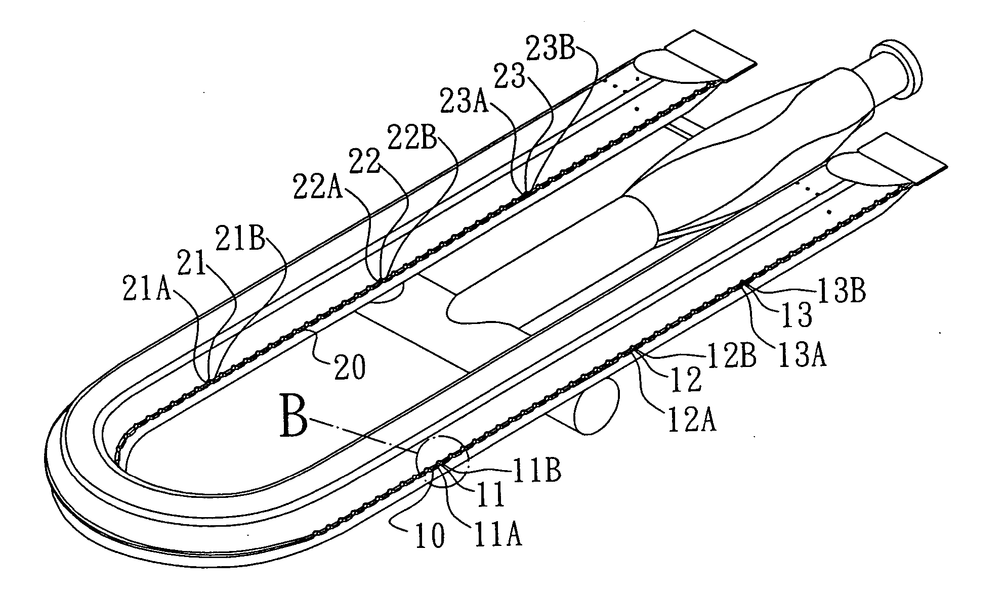
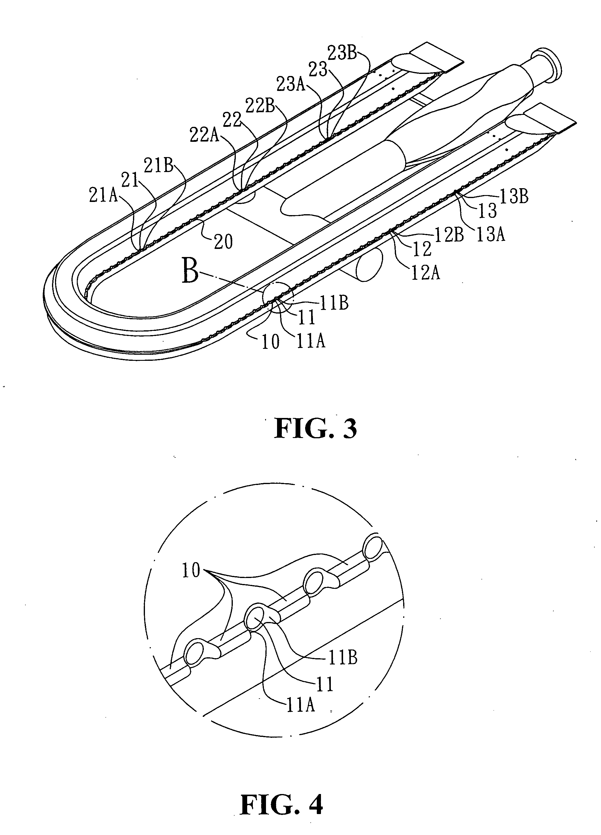
[0022] Referring to FIGS. 3 through 8, a first preferred embodiment of the present invention is related to a U shaped thin tube burner provided with multiple flame holes 11, 12, 13, 21, 22, 23 in rows respectively disposed on both sides of the tube. Both sides of the tube are punched into multiple walls 10, 20 in a shape of a lip slightly protruding from the sides of the tube. Those flame holes 11, 12, 13, 21, 22, 23 are punched at an angle practically vertical to the tip of the lip through the...


PUM


Abstract

A tube burner flame hole construction with both sides of the tube provided with a row of multiple flame hole walls; each wall being compressed in a shape of a lip with both sides slightly protruding outwardly from the tube; a hole being provided in the center of the recessed lip to facilitate the punching process and improve structural strength of the of the entire tube burner, flame hole being more sturdy and thicker for consistent burning effects and longer service life of the tube burner.

Description

BACKGROUND OF THE INVENTION [0001] (a) Technical Field of the Invention [0002] The present invention is related to an improved construction of flame holes on a tube burner, and more particularly to one that provides walls housing those flame holes improved structural strength, consistent burning effects and longer service life of a burner generally used for a mantelshelf in a restaurant. [0003] (b) Description of the Prior Art [0004] The oven used in a mantelshelf in a restaurant is usually different from that of a domestic one, and the structure of the burner in the mantelshelf is also drastically different from a domestic burner. So far, the commercial burner is usually made in an “T” or a “U” shape. The tube burner is adapted with an inlet of fuel gas connected to a source such as a gas cylinder. All other openings are sealed either by press or welding. Both sides of the tube are disposed with multiple minute flame holes in a row so that when the fuel gas is admitted, the fuel ga...

Claims


Application Information

Patent Timeline
Patent Type & Authority Applications(United States)
IPC IPC(8): F23D14/46
CPCF23D14/06F23D14/105F23D14/46F23D2213/00
Inventor HOME, WILLIAM
Owner GRAND HALL ENTERPRISE COMPANY
Why Eureka
Try Eureka